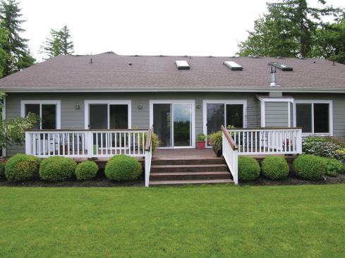
The original plan was to simply replace the treated decking on t…
The original plan was to simply replace the treated decking on the existing rear deck.
Kim Katwijk
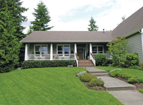
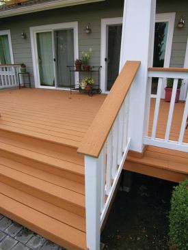
The homeowner wanted the new deck railing to have tapered posts …
The homeowner wanted the new deck railing to have tapered posts that matched the style of these columns on her front porch.
Kim Katwijk
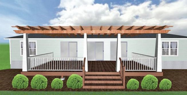
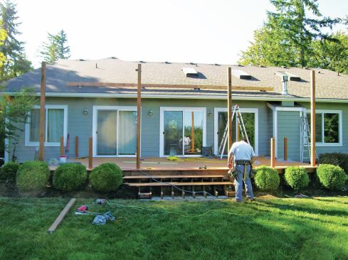
The author used a CAD program (Realtime Landscaping Architect) t…
The author used a CAD program (Realtime Landscaping Architect) to create 3D renderings of his pergola proposal, which helped sell the idea to his client.
Kim Katwijk
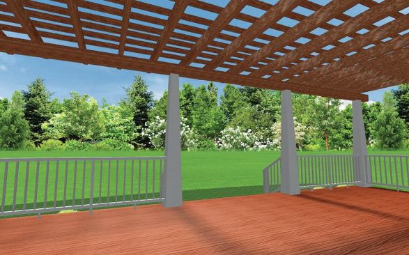
CAD-generated 3D renderings showing the pergola from different d…
CAD-generated 3D renderings showing the pergola from different directions helped the client visualize it.
Kim Katwijk
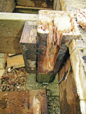
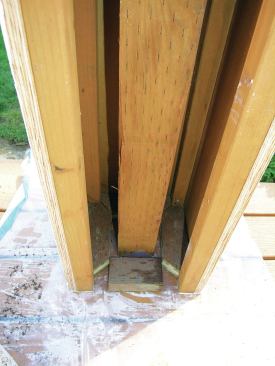
Fastening the treated rail posts directly to the framing created…
Fastening the treated rail posts directly to the framing created a collection zone where water and organic material were trapped, causing the adjacent wood to rot.
Kim Katwijk
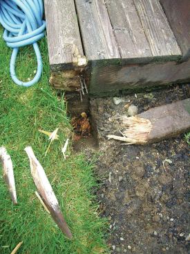
The stair posts, which had been buried in the ground, had also r…
The stair posts, which had been buried in the ground, had also rotted.
Kim Katwijk
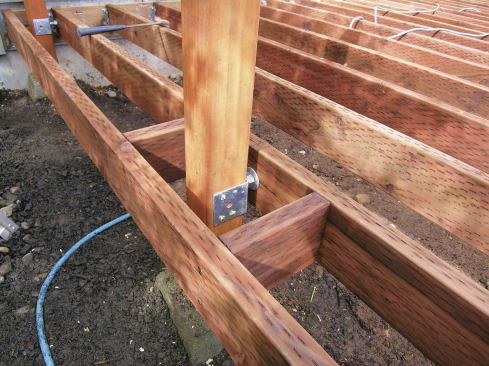
To provide a drying airspace around the posts, the author attach…
To provide a drying airspace around the posts, the author attaches them to the horizontal framing with post brackets.
Kim Katwijk
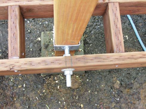
The bracket’s 3/4-inch-diameter saddle bolt must be securely f…
The bracket’s 3/4-inch-diameter saddle bolt must be securely fastened with a nut and washer on each side of the joist. Another post bracket (not visible in the photos) attached to a concrete pier keeps each post from contacting the ground.
Kim Katwijk
Blocking around the post bases holds the bottom of the column in…
Blocking around the post bases holds the bottom of the column in place and helps keep it square.
Kim Katwijk
Tapered 2x2s at each corner provide support for the MDO panels t…
Tapered 2x2s at each corner provide support for the MDO panels that will form the face of the tapered columns.
Kim Katwijk
To conceal the rough edges of the panels, 1-by trim is nailed in…
To conceal the rough edges of the panels, 1-by trim is nailed into a bed of caulk at each of the corners.
Kim Katwijk
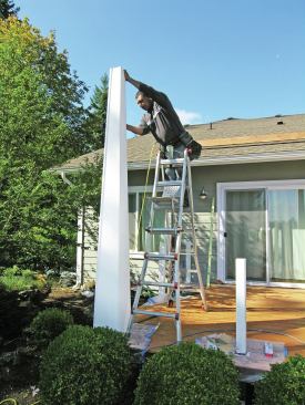
4×4 posts bearing directly on the wall plate support the pergola…
4×4 posts bearing directly on the wall plate support the pergola beam located above the roof.
Kim Katwijk
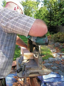
The pergola rafter tails feature a reversed-curve profile. First…
The pergola rafter tails feature a reversed-curve profile. First, the author makes a 45-degree cut at the corner of each rafter to quickly remove excess material.
Kim Katwijk
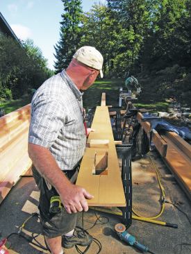
A simple plywood jig makes cutting the rafter tails easier.
Kim Katwijk
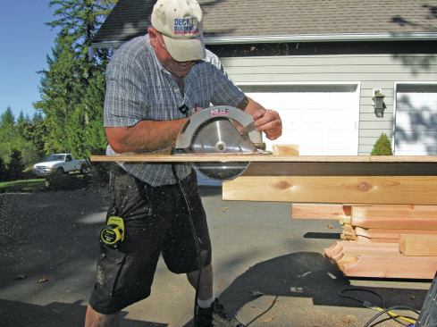
Using his jig as a guide, the author roughs out the curve with a…
Using his jig as a guide, the author roughs out the curve with a 10-inch circular saw.
Kim Katwijk
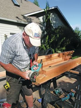
After smoothing the profile with a sander, the author eases the …
After smoothing the profile with a sander, the author eases the edges with a round-over bit mounted in a router.
Kim Katwijk
Kim Katwijk
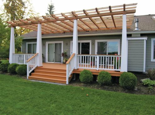
The painted rail posts, balusters, and tapered pergola columns c…
The painted rail posts, balusters, and tapered pergola columns contrast nicely with the composite decking and naturally-finished cedar pergola beams and rafters.
When I work with prospective clients, I listen carefully to what they say they want, and prepare a proposal that meets their requests. But I also try to upsell projects by offering the clients additional options they may not have thought of. The project featured in this article is a good example of that approach; if I hadn’t suggested adding a pergola to the basic deck design, the client wouldn’t have realized that it was even a possibility.
Initially, my client simply wanted to replace her weathered pressure-treated 2-by deck boards with wider composite decking. She hoped that I could build new corner posts and stair-railing posts that would match the tapered columns on her front porch. Later, when I drew up the 12-foot by 28-foot deck design, I created one set of plans that matched her request, as well as a second set that included a pergola. She was happy enough with the first set of plans, but she was thrilled when she saw the pergola — and immediately signed the contract, despite the $6,000 the pergola added to the project budget.
Framing
The existing deck was in rough shape. When I cut away the old deck and railing, I wasn’t surprised to discover rot in the railing posts, even though they had been built with treated material.
Encasing posts by attaching them directly to the deck framing is a common practice, but unfortunately it creates what I call a collection zone, where water and organic matter get trapped — a perfect environment for rot. To prevent this problem, I attach railing and other vertical support posts to the framing with galvanized adjustable post brackets. One bracket suspends the post between framing members, while another bracket conventionally installed on the bottom of the post (in combination with a pier block) holds it off the ground. The resulting air space around the post promotes drying. These brackets have not been tested by their manufacturers for this use, however, so if you use this detail, be sure to get approval from your local building inspector.
To help keep the wood from rotting, I always treat bolt holes and other cuts in treated lumber with 9% copper napthenate end-cut solution, which I buy at my local Home Depot. Also, when I install decking, I leave a 3/8-inch gap all the way around each post so water and debris can drain easily around it.
Column Construction
Once the framing was completed and the composite decking installed, I put a piece of 6-mil plastic sheeting over the top of each post and slid it down. The protective plastic makes it easier to paint the tapered columns after assembly. It also serves as a barrier against insects that might try to build nests inside the columns.
I built the tapered columns that wrap around the vertical supports using 3/4-inch MDO (medium density overlay) paper-faced plywood. First, though, I installed small pieces of treated 2x4s around the base of each post to hold the bottom of the column in place and keep it square. Then I ripped treated 2x2s to match the taper so the MDO panels would fit tightly at the top of each post.
I ripped the MDO panels to size — when assembled, the columns would measure 41/8 inches wide at the top and 14 inches wide at the bottom. For each column, I fastened three tapered panels together and positioned the assembly around a post. After nailing the three sides to the post and the tapered 2x2s, I installed the fourth panel. To finish off the columns before painting, I fastened 1×1 cedar strips to the corners to conceal the exposed edges of the plywood.
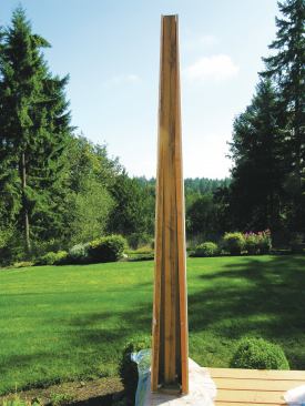
Pergola Beams
A 28-foot 4×8 architectural C-grade kiln-dried red cedar beam that would bear on the wall plate needed to be installed above the roof. Since there was no attic access to the plate, I estimated its position and the location of my four 4×4 support posts, then cut exploratory 1 1/2-inch-diameter holes through the shingles and sheathing with a hole saw. The small holes allowed me to verify the exact location of the wall plate and roof trusses, and tweak the support-post locations accordingly.
I finished cutting the holes through the roof sheathing with a reciprocating saw, working carefully so the posts would fit tightly in the openings. I fastened the posts to the plate with 3/8-inch by 16-inch-long structural screws, four per post, driven into the plate at an angle.
I sealed the gaps between the sheathing and the posts with Henry 900 Flashing and Construction Sealant (800/486-1278, henry.com), applying it to the edges of the roof cutouts before installing the posts, then forcing more sealant into the gaps after driving the lag screws into the plate. After tooling the sealant smooth, I flashed the posts with metal L-flashing.
Another red cedar beam spans the top of the columns. To make solo assembly easier, I spliced each beam together in sections, with the butt joints located on top of the supports. I attached the beams to the posts with pairs of 3/8-inch by 16-inch structural lag screws (screw-products.com) at each connection point.
Rafters
When I lay out rafters, the spacing depends on how much shade the client wants the pergola to provide. On this project, my client didn’t want to block too much sun — not surprising here in the cloudy Pacific Northwest — so I spaced the 4×6 cedar rafters 24 inches on-center.
The rafters have a reversed-curve profile on each end, a detail I like to offer. Before cutting the curves, I clipped 45-degree corners off the ends of each rafter with my chop saw. I then roughed out the profile with a 10-inch circular saw guided by a simple plywood jig. To shape the tails, I set the saw on the jig, made multiple cuts to carve out the wood, then slid the saw side to side to smooth out the cut.
I finished up the reverse curves by grinding out any rough areas with an angle grinder, then smoothing the profile with a random orbit sander and 120-grit paper. Afterward, I rounded the edges over with a router.
I fastened the rafters to the beams with 3/8-inch by 10-inch lag screws driven down through the tops of the rafters, using one screw per connection. Then I fastened 2×3 cedar purlins (on edge) to the rafters with 1/4-inch by 6-inch lag screws. When pergola rafters are on 2-foot centers, 16-inch purlin spacing looks good; when rafters are on 3-foot centers, I typically space the purlins 19-inches.
Since the cedar stock I use is cut green and contains a lot of moisture, I usually allow it to air-dry for a couple of months before I apply a finish. On this project, I sealed the cedar with Sunfrog semi-transparent penetrating stain, and painted the columns with two coats of latex paint over primer.
Railing
The railing consists of 2×2 balusters sandwiched between 1×3 top rails and 1×4 bottom rails (all cedar), capped at the top with an EverGrain (800/641-4691, tamko.com) deck board. I pre-finished all the rail components, then cut the rails to fit the tapered columns. I pin-nailed one side of the top and bottom rails to the columns and posts with stainless steel nails, marked the baluster spacing on the rails using a story pole, nailed the balusters in place, then installed the second set of rails. To finish up, I screwed the cap boards in place.
Contributing editor Kim Katwijk is a deck builder in Olympia, Wash., and his wife, Linda, assists with his writing.
Kim Katwijk is an internationally known deck designer and builder with 45 years of construction experience ranging from heavy commercial building to log home construction.However, his true love is designing and building decks—which he has done for the past twenty years. Kim is known for his articles in Professional Deck Builder Magazine as a contributing editor for the past 11 years. Kim and his wife, Linda have also published feature articles in The Journal of Light Construction and Fine Homebuilding. He teaches The Deck Clinic at Deck-Expo and JLC Live shows and has taught several “how to” classes in South Africa, Canada, and other national trade shows.Kim established Deck Builders, Inc. in 1996. He lives in Olympia, Washington, has been happily married for 38 years, and is the father of 10.