A client I had helped complete a two-story addition and kitchen remodel a few years ago recently contacted me about building a deck and pergola. He sent some rough outdoor-living concepts to me, which I drew in SketchUp. After a few go-arounds, he settled on a design he liked.
The client found and purchased the new pergola system online. The manufacturer was Steel Shade Pergolas located in Tulsa, Okla., a fair distance from sunny Southern California. After the usual delays at the building department, the owner obtained a building permit, which is when I got a look at the pergola manufacturer’s plans. The first thing that struck me was the size of the footings: 4 feet square by 2 feet deep. Also, I noticed that the pergola was powder-coated steel—with the largest steel member weighing in at roughly 275 pounds.
I contacted the manufacturer to find out why the footings needed to be so large. Though heavy to install, the finish pergola didn’t weigh all that much. I was told that because the company sells pergolas nationwide, it has a universal structural design primarily focused on wind loads. Per the manufacturer’s data, these pergolas can withstand a substantial wind load of 110 mph in an Exposure B urban-suburban setting. Where this house was located, in the center of Los Angeles, it would likely not experience wind speeds that great; though in nearby Malibu, the Santa Ana winds can reach 70 mph or higher (in December 2011, the Santa Anas were clocked at a continuous 97 mph with gusts up to 167 mph in Malibu).
Planning for a Steel Pergola
As with the kitchen remodel project, the homeowner wanted to do some of the work. He was a capable, hands-on type of client; he did a nice job building all his kitchen cabinets in his garage on his off time. So, we divvied up some of the tasks. He wanted to dig the footings, and later, install the deck boards with low-voltage LED lighting for the treads; this left installing the footing rebar and concrete, erecting the steel pergola, and framing the deck to me and my crew. He also would select the canvas shading he wanted to use on top of the pergola and install it himself at a later date.
Footings. The pergola design called for three footings laid out in a L shape. After the homeowner excavated the holes for the footings per the manufacturer’s on-center spacing, we began to set the forms and set the rebar. The structural drawings called for two mats of #4 rebar at 10 inches on-center in each direction, top and bottom. For the concrete-pier-to-steel-column connection, one of the approved footing designs had a raised 16-by-20-inch-by-8-inch-high center section. We opted to go with this “columns extension” design so the base of the pergola’s steel columns would be a couple of inches above grade to avoid rusting (the local soils are clay and typically hold water in winter).
To reinforce the raised center section, we had 12 “hairpin” U-shaped bars bent for the three pier footings. The manufacturer supplied plywood templates to lay out the four galvanized anchor bolts, which secured with double nuts, one below and one above the plywood.
The hairpins were then tied together to form a box shape around the 3/4-inch-by-16-inch-long anchor bolts. We wrapped the #4 hairpins with #3 rings to hold them together (similar to a grade-beam rebar-cage assembly) (Figure 1).
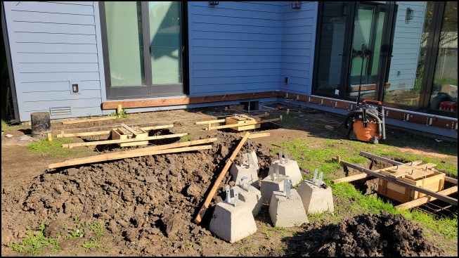
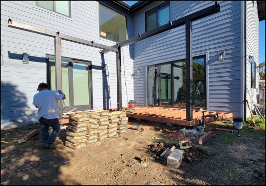
Figure 1A. In front of the southwest-facing kitchen, the pergola footings are laid out in a L-shape pattern.
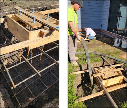
Figure 1B-C. A raised center section of the footing is formed with 2-by stock nailed to wood supports spanned over the excavated holes. A plywood template precisely holds four anchor bolts in position during the pour (left). Pea-gravel concrete (3,000 psi) is pumped into place (right).
Important to the foundation layout was that the columns be spaced accurately and oriented exactly 90 degrees to each other—being off here could be an expensive mistake. Since the nuts could be raised or lowered to fine-tune the level of the column base plates, being perfectly level with each other was also a consideration but not as important. For the column layout, measuring off the building wasn’t an option because it was out of square. Instead we used a PLS 5 laser to shoot the templates holding the anchor bolts to make sure they were square and spaced correctly.
To align the footing forms so they were square and parallel to the kitchen exterior wall, I pounded rebar pins in the dirt and tied string to them. We then spanned wood supports over the hole and nailed 2-by forms for the raised centers to the supports. We suspended the top rebar mat from the wood supports with wire and supported the bottom mat on blocks placed on the bottom of the hole; the rebar “cages” were tied off to the rebar mats. For the center footing, at the inside corner of the “L,” we roughed-in electrical conduit for future lighting and power; the homeowner didn’t want to pay an extra $2,000 for the factory lighting.
The inspector had come and approved our work and we were just about to pour the concrete when the rain began. As the holes for the pier footings in the clay soils filled with water, the bottoms softened into sticky brown mud. What was supposed to take a couple of days stretched out into a couple of weeks. Pumping the water out did little, so the owner removed our steel and forms. Sunny skies returned, the pads dried out, the owner dug out the fallen-in mud, and we had to redo the formwork.
To finish up the footings, we pumped 3,000-psi pea-gravel concrete into the holes. I have found over the years that going with a 3,000-psi concrete instead of 2,500 psi helps reduce cracks and gives my finishers more “cream” to work with to achieve a nice finish in addition to the extra strength.
Erecting the steel. The truck with a gooseneck trailer arrived bearing the steel. The three steel posts and two steel beams fabricated from 6-by-6-by-3/16-inch tube stock weighed anywhere from 150 to 275 pounds each (the biggest beam took five men to carry it to the backyard). Also included in the load were nine 2-by-4-by-3/16-inch steel rafters.
Starting out, we chipped away some of the green concrete to create a recess for the dry pack under the base plates. Then we set the height of the bolts with a laser so they were all uniform. The three posts arrived with 10-by-14-by-3/4-inch-thick A36 steel base plates welded to the bottom with web stiffeners. Two posts were 10 feet 6 inches high, while one was 9 feet 9 inches high.
We lugged them in place, stood them on the bolts, and loosely tightened the upper nuts. Steel can move or warp when it’s being welded due to the high heat of the MIG or Stick welder, but here we didn’t have to reject any warped pieces. Then, we raised and lowered the nuts until the three columns were level and plumb with each other (Figure 2).
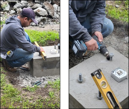
Figure 2A-B. The bottom nuts are leveled (left), concrete is removed from anchor bolt threads and the bottom nuts are screwed on as needed (right).
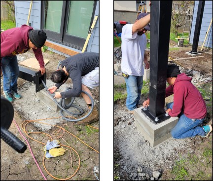
Figure 2C-D. Wiring for lighting is fed through the middle tube-steel post (left). The last of the three factory-welded steel base plates is temporarily set—the upper nuts loosely tightened (right).
With the columns in place, we could install the beams. I rented a manual fork lift and we hand-cranked the heavy beams up, then jockeyed them in place for bolting (Figure 3). Since the tubes were raw steel on the inside, we applied black silicone caulking around the nuts and washers to keep water out.
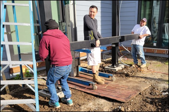
Figure 3A. The homeowner (at center in photo) helps wrangle the first beam into place with the help of a Genie lift.
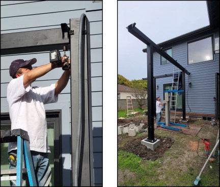
Figure 3B-C. The beam is bolted to the posts (left), then the second, longer beam is hoisted into place and secured (right).
Next, we set the base plates into their final position, tightening down on the top nuts, then began to dry pack the plates. We used Rapid Set Blue high-strength grout for our dry pack (I prefer using the Rapid Set Blue rather than a traditional dry pack of sand and Portland cement). One of the crew members mixed it in a tray while another member and I packed it in firmly in place to fill any voids, to an approximate 1-inch thickness (Figure 4).
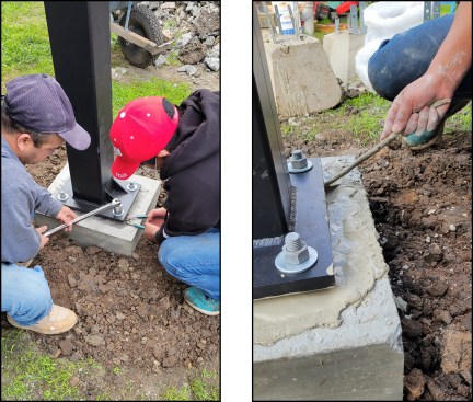
Figure 4A-B. The base plates are set in their final position (left). High-strength grout is packed firmly in place about 1 inch thick to fill any voids (right) …
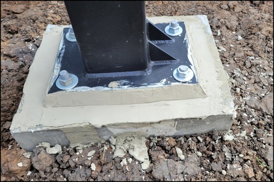
Figure 4C. … then tooled at an angle (C).
Over the next few days, we framed the deck out of treated lumber 2-by stock (working around the steel columns), poured concrete pads for the stringers, and loaded the excess soil in a low boy for haul off. My next order of business was to rent scaffolding, erect it, and place the rafters on the horizontal beams (Figure 5).
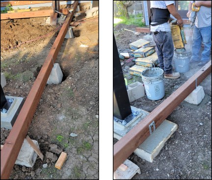
Figure 5A-B. For ease of leveling, the precast piers are first attached to the wood beams (left) and leveled, then set in concrete pads (right).
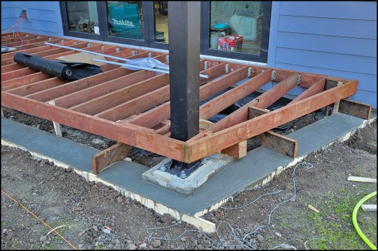
Figure 5C. The deck is framed around the steel columns.
I purposely delayed installing the rafters until after the deck was framed so the man on the receiving end of the rafters would have a flat stable platform to set the ladder on. We laid shipping blankets on the beams and the scaffolding to protect the powder coating from scratches. Despite our efforts, there were a couple, and the manufacturer provided the homeowner with a spray can of powder coat touch-up paint.
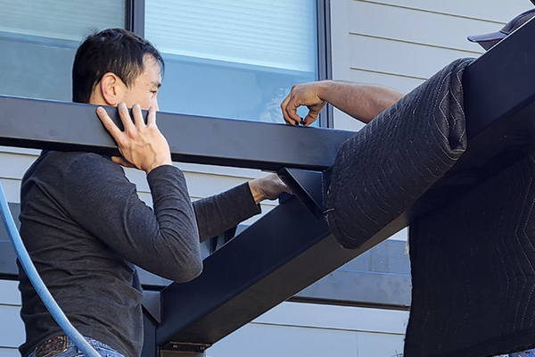
The nine 2-by-4-by-3/16-inch steel rafters came in two lengths, 4 feet 7 inches and 6 feet 7 inches, with fairly long cantilever lengths. Two welded brackets on either side of the beam marked rafter locations. We set each rafter on top of the brackets and ran a bolt all the way through it to secure it on both sides of the beam. Steel Shade Pergolas designed the connection to withstand wind loads in our environment. We caulked the bolts to prevent water from entering the tube-steel rafters and getting trapped (Figure 6).
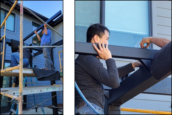
Figure 6A-B. The tube-steel rafters are bolted to welded brackets on both sides of the beam. Shipping blankets on the beams and the scaffolding protect the steel’s powder coating from being scratched during installation (left, right).
Finishing up. With the precision of a cabinetmaker, the homeowner did a nice job installing the deck boards with low-voltage LED lighting for the treads (Figure 7). He planned to install canvas-style shading, rather than the more traditional wood-slat shading, for aesthetic reasons (as of this writing, he has yet to complete this work).
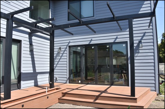
Figure 7A. The finished pergola frame. The homeowner will install canvas-style shading, which will keep afternoon sun from pouring into his kitchen.
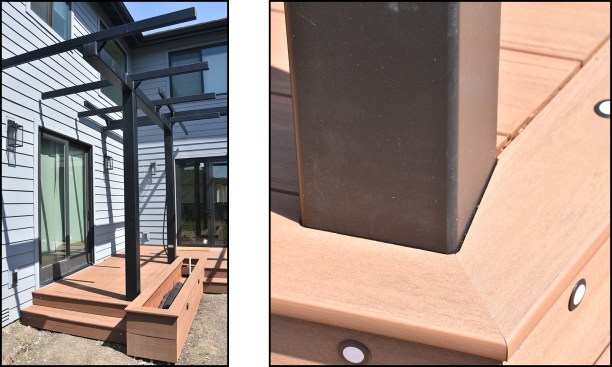
Figure 7B-C. The finished pergola frame and planter (left). Low-voltage LED lighting installed at riser locations (right).
The Steel Shade pergola is, for all intents and purposes, a giant erector set. It had a well-thought-out design and it bolted together glitch-free. All it took on my part was a careful layout and using the right equipment to lift the pieces in place. My part of the project was about $4,400, while the homeowner paid for the steel and decking—he didn’t divulge his costs.
Photos by Gerret Wikoff