Along a 250-foot driveway through a heavily wooded area are two utility poles that led to one of my recent projects. These poles support overhead service lines for power, telephone, and cable and connect to the house basement through underground cables. PSE&G, the electric utility company, offered unmetered service for light fixtures mounted to the poles. In 1982, two 100-watt MV (mercury vapor) pole light fixtures were installed with photocells for dusk to dawn illumination. Service was billed monthly with a fixed charge for the light fixtures plus electric energy and delivery charges, which varied from month to month based on estimated kWh consumption.
The original two-fixture charge was $12.90 per month and had increased to a modest $14.88 by 2024. Then, the fixture charge jumped to $41.32 without any notification or explanation. The cost for estimated 1,010‑kWh annual energy consumption was $98.80. The total annual operating cost was now $594 ($297 per light) for the original lighting.
I investigated alternative lighting with one energy-efficient LED luminaire near the house. I liked the downlight distribution of pole lights and searched for streetlight fixtures. To match the brightness of the existing pole lights, I needed only 25 watts for LED lighting. The electrical energy consumption would be a quarter of what it had been and even less with timed operation.
Site Conditions
Underground service runs from the utility pole to a meter outside the west side of the house. Also, two 1-inch poly tubes run from the pole location to the basement. One houses cable service. The other was intended for future landscape lighting. The dusk-to-dawn PSE&G 100-watt MV pole lights illuminated the driveway near the street connection and in front of the garage. The light output of such lamps is typically about 4,000 lumens at 4000K (Kelvin refers to the color temperature).
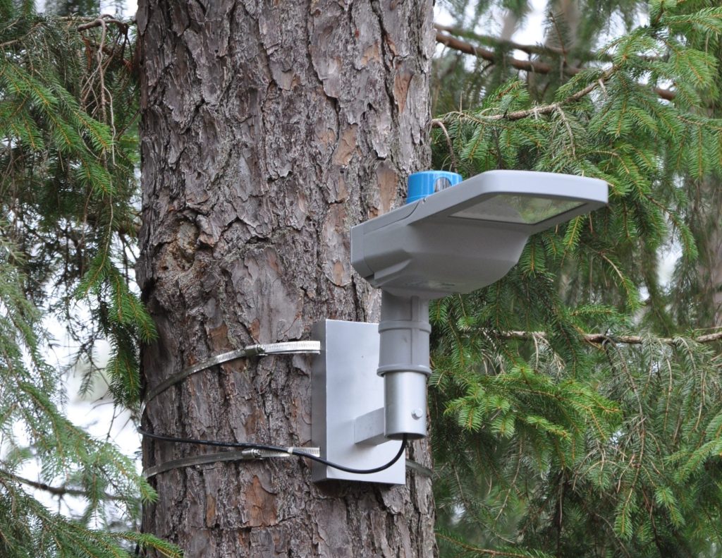
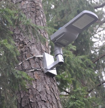
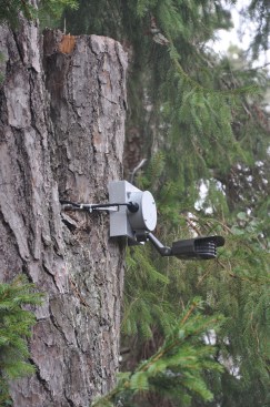
A large pine tree 12 feet from the second utility pole turned out to be a suitable mount for a streetlight-type luminaire directed toward the house and away from neighboring houses. To replace the pole light, we could simply pull a new cable into the existing conduit and connect it to the breaker panel to feed an LED luminaire equipped with a photocell.
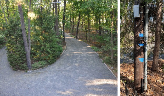
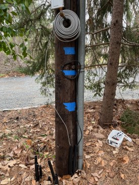
Before. Utility service runs underground from a utility pole near the end of the driveway to the house, and a light was mounted on this pole (left). The author pulled cable from the basement breaker panel through an existing conduit (right) to feed a light mounted on a pine tree 12 feet away.
Planning and Design
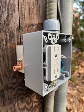
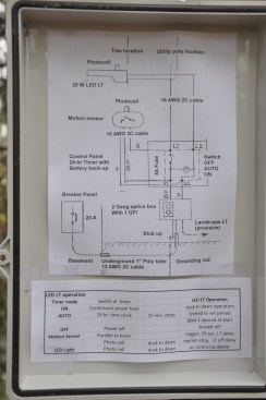
To keep the provision for landscape lighting, I decided to install a splice box at the utility pole and a GFI outlet at that location. The cable to the luminaire would rise along the pole and drape to the light fixture mounted with a custom-made bracket to the tree. The first design for the support called for welding the aluminum parts, but the cost was too high. I changed the design to a bolted version, obtained the parts for less than $50, and did the simple fabrication.
To replicate the 100-watt MV pole light, a 25-watt LED streetlight would do. Such luminaires are readily available with lenses for various light distribution patterns and optional add-on shields. The area to be illuminated is some 40 by 40 feet, and the mounting location required a “forward” light direction. After evaluating several options, we chose a ZGSM-ST17-25S model with 3,875-lumen output from Hangzhou ZGSM Technology and a shield to limit backlight. I specified 3000K, an optic to suit the area of illumination, and a three-pin photocell.
LED streetlight fixtures have a driver to power the light and allow dimming with remote control. However, such controls are designed for utility applications with sophisticated control devices, not for residential use. For solar-type LED, I found a company offering a smartphone app to set times and dimming levels, coupled with a motion sensor. It represented my preferred control mode, but solar powering was not practical for the tree-shaded site, and I could not find a similar system for 120-volt applications.
ZGSM can factory-set a dimming program, but changing it on site requires a utility-type control device. ZGSM also offers a control with a motion sensor, but a combination of dimming and motion control was not available. Another company offers an eight-position selector switch at the light fixtures to set the lumen output, which could be helpful to tune the lighting application. However, I decided to build my own add-on control feature for the ZGSM fixture we chose, using a timer to shut the light off at a certain time and a motion sensor to turn the light back on as needed. The luminaire’s photocell turns the light on at dusk, the timer shuts it off at a set time, and the motion sensor control takes over. This control mode is mindful of neighbors and follows the “dark-night” initiative.
For simplicity, I selected a mechanical 24-hour timer switch (TB 388) with battery backup. It has a control selector switch: Auto (timed operating mode, photo cell turns the light on during the set time allowed), On (dusk-to-dawn lighting controlled by the photo cell), and Off. For motion detection, I selected an RAB Lighting Stealth STL200-LED. It offers a 200-degree, 50-foot detection pattern and comes with add-on shields to restrict the angle. It also has a built-in photocell. The sensitivity, photocell operating mode, and the off-delay after motion detection ceases are all adjustable.
Prep Work
I fabricated a support to mount the light fixture to a 20-inch-diameter tree. The bracket consists of three aluminum parts—a 5-inch channel, a 1 1/2-inch-square tube, and a 2-inch Schedule-40 pipe—held together with a 3/8-inch bolt. I cut slots in the legs of the channel for stainless-steel mounting straps and drilled the bolt hole. I shaped one end of the square tube to match the pipe diameter and inserted a wood pin to locate the position of the bolt that would hold the channel, tube, and pipe together. After drilling the bolt holes and cleaning and sanding with 150 grit, I bolted the parts together. I primed and spray-painted the assembly metallic gray.
Likewise, to fabricate a base for installing the motion detector to the tree, I drilled and tapped holes in 5-inch channel and fastened a 4-inch outdoor-type metal box to it.
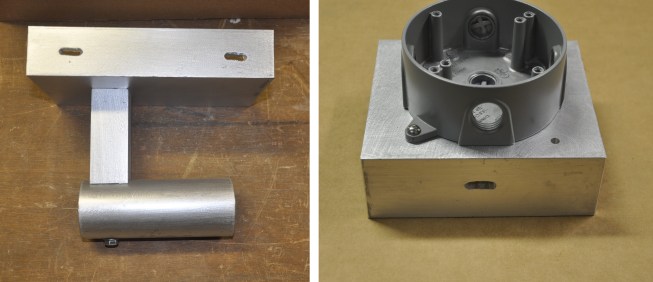
Mounting brackets: The author fabricated aluminum mounting brackets for the light and the motion detector. Slots in the bases allow for securing the brackets to the tree with stainless steel strapping.
I set up the LED light fixture with the fabricated support in the workshop for testing, connected a power cord, installed the photocell, and plugged the cord into an outlet. The LED light blinked for a second. I turned off the shop light and the LED turned on after a 10-second delay. With the shop light turned back on, the LED turned off after a three-second delay. In dusk-to-dawn operation, such delays will not be noticed; however, for triggering with a motion sensor, the 10-second delay before turning on is longer than I had hoped, but acceptable.
Mounting the back shield to the fixture required some modifications. The hole diameter at the fixture was 4mm and not tapped. The supplied M5 socket cap screws have a 4.8mm diameter. I drilled the hole to 4.3mm and cut #8-32 threads for standard stainless-steel screws.
Installation
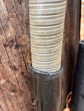
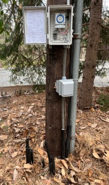
I pulled a 12 AWG 2C cable (Southwire copper UF-B) through the 95-foot-long, 1-inch-diameter poly tube. At the pole, I mounted a two-gang metallic outdoor box and installed one GFI double outlet. The larger box provides extra space for cable splicing. I installed a 5/8-inch-by-8-foot-long copper-clad-steel ground rod and connected it with 6 AWG bare copper to the splice/outlet box. There seems to be no special fitting for a poly-tube-to–flexible-conduit connection. Luckily, the flex conduit fit snug inside the poly tube. I added a hose clamp and taped the joint for a watertight connection.
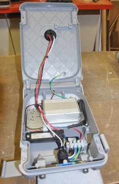
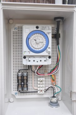
I installed the timer switch on the back board inside an 11-by-7.5-by-5‑inch waterproof IP67 ABS plastic box with a hinged cover and lock provision. I added a fuse holder and a 5-amp fuse to use 16 AWG wiring for the light fixture (2C) and the motion sensor (3C). I mounted the control box 56 inches above ground at the pole and connected it with liquid-tight flexible conduit to the splice/outlet box below. I affixed the control schematic and LED operating mode on the inside of the control box cover (see photos 10 and 12, above).
The height of the light installation needed serious consideration. Interpreting photometric test reports and diagrams for a specific lighting application may require help from experts. I submitted an area arrangement sketch to ZGSM, and an agent helped guide me for the lens selection and mounting height range. I chose 14 feet for the fixture mounting height. Stainless-steel bands strap the support bracket to the tree, and the mounting height can be adjusted by moving them up or down, if required. The supplied luminaire attachment fitting allows for +/-15 degrees adjustment from level and sideways swivel on the support pin.
The manual for the motion sensor suggests a mounting height of 6 to 12 feet for optimum range and detection. A diagram shows a 50-foot-distance by 100-foot-wide detection range at a 10-foot mounting height. I selected an 8-foot height for this installation. I mounted the bracket with stainless-steel straps as I did with the light, so it can be moved, if required. Upon energizing, the motion sensor starts with a 15-minute test period, which allows for making adjustments and tuning.
Controls and Adjustments
I set the light timer window from 6 to 9 p.m. During that time, the photocell located on top of the light fixture turns on the light depending on the natural light level. At 9 p.m., the timer shuts off the light, and the motion sensor control, which is connected in parallel, takes over. When motion is sensed within its detection range, the sensor turns on the light with a 10-second delay (I kept the factory settings for the motion sensor).
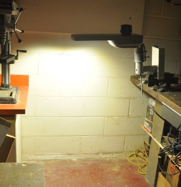
In the shop, the author tested the light before installing it: H…
The selected mounting height for the light fixture and motion sensor proved correct. After some operating time, I adjusted the luminaire angle to +15 degrees from level, to increase the forward light projection toward the garage front. I did not mount the back shield, since the lighting effect on the surrounding trees is pleasing.
Bottom Line
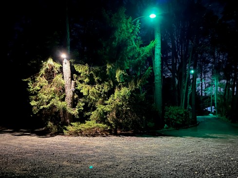
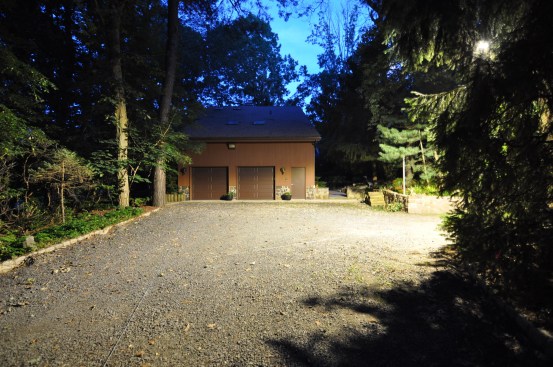
After we installed the new LED light, the old MV lights remained operational until PSE&G finally removed them, some time later. This afforded a comparison of the two lights, and it was clear that the warmer, 3000K LED light is more pleasing than the 4000K utility light.
The author mounted the brackets holding the LED light fixture to…
The two utility pole lights along the driveway were eliminated. The one near the street was never necessary. The one near the house was replaced with a tree-mounted, high-efficiency LED luminaire. Timed operation drastically reduces electrical energy consumption and “light pollution.”
The total material cost for the installed system with one luminaire and controls is less than the previous annual fixture utility charge for two pole lights. The annual electrical consumption with timed operation is less than 30 kWh from metered service, compared with 500 kWh for estimated unmetered service (at a lower rate) for each dusk-to-dawn utility light.