Sue Burnet
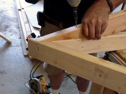
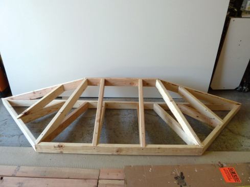
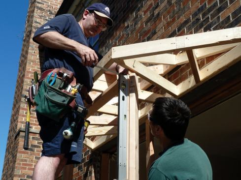
The "ridge" is screwed to the tops of the common rafters.
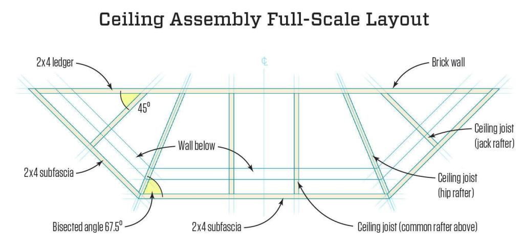
Calculating the tough angles
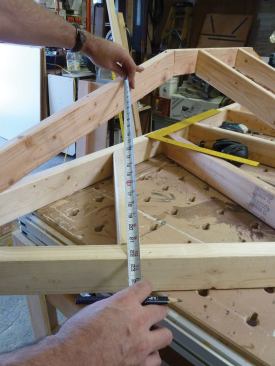
Once the ridge was in place, we found the length of the two nailers that would run from the ends of the ridge to the outside of the subfascia by simply measuring with a tape. But the pitch was different from the pitch of the commons, so we still needed to figure out the angle for the plumb cut and complementary seat cut. There are many ways to figure out these angles, including scribing, but I went back to the construction calculator because of its accuracy.
First I entered the run, taken from the template, and the rise, measured from the ceiling framing to the top of the ridge. I hit “‘Diag” to give me the length (which I’d already measured) and then hit “Pitch” once to give me the pitch in inches, and a second time to display the pitch in degrees. The angle of the plumb cut was 15.93 degrees, which I rounded to 16 degrees. For the heel cut, I used the complement of that angle: 74 degrees. We used a similar method to measure and fabricate the hip rafters. The plumb cut for the hip rafter also needed to be cut with a bevel angle, which we took from the corresponding joist below.
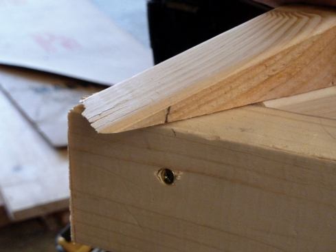
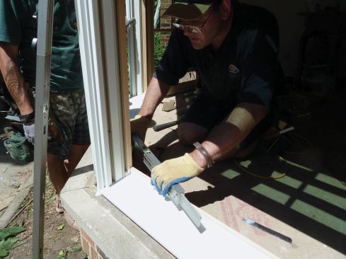
I’d measured and cut the nailers to the long point of the subfascia, so the ends of the nailers stuck out beyond the edge of the subfascia, which put the edge of the nailers above the roof plane. We could have beveled the entire length of each nailer, but we decided to “drop” them instead to put the inside top edge in plane to catch the roof sheathing. To find the drop, we held the nailer in position on top of the joist, then struck a plumb line on its face where it overhung the framing below. The height of the line (about 3/8 inch in this case) equaled the amount of drop. I scribed this distance along the heel cut, then trimmed off that amount so that we could install the nailers at the proper height.
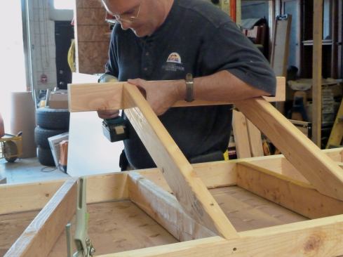
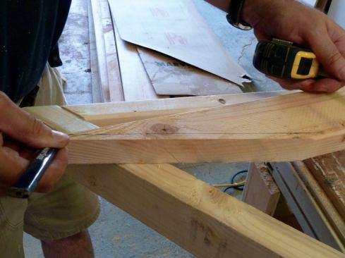
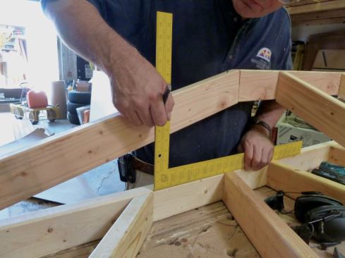
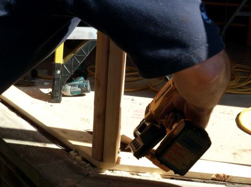
I call the last two rafters jack rafters, although technically they are probably hybrids. First we marked their location on the nailers with a framing square placed on the ledger, and measured their length directly from the roof assembly. We cut compound angles at the top ends of the jack rafters, with the plumb angle the same (5 in 12) as the commons, and the bevel angle at 45 degrees.
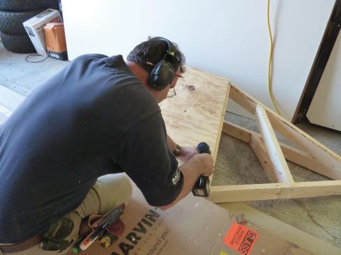
We also cut the roof sheathing sections while the bay roof was sitting on the bench. We measured each section and transferred the dimensions to 1/2-inch CDX plywood. Because we would need to access the roof framing to secure it to the house, we just tacked the sheathing in place and then removed it.
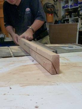
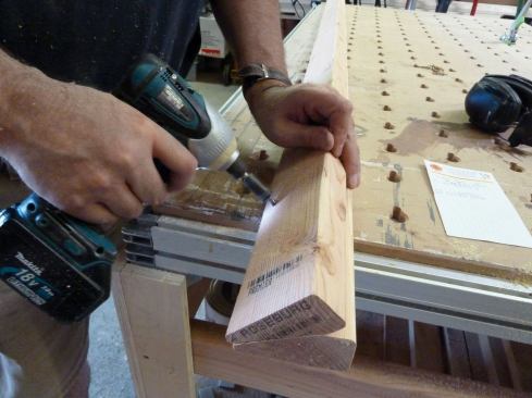
The last pieces made in the shop were the posts for the angled corners where the walls would meet at 45 degrees. We used our template to lay out the profile of the posts, transferring the dimensions to a section of 2×4. For each post, we ripped a bevel on one side of a pair of 2x4s, then screwed the pair together on the bench to ensure a straight corner post.
Assembling the bay on site
The following day we returned to the site with all the parts for the bay. We cut two sets of plates: 1×4 bottom plates to set the windows at the correct height; and 2×4 top plates. We nailed the bottom plate to the existing sole plate and toe-nailed our angled corner posts to those plates. Then we nailed the middle top plate to the tops of the posts to set the roof when we lifted it.
The roof assembly weighed around 50 pounds, making it easy to lift and position on top of the front wall. We supported the inboard side of the roof temporarily with a 2×4 post. The corners of the top wall plate bisected the angled lookouts, so we positioned the wall, plumbed it, and secured it to the center ceiling joists. We also secured the ridge, ledger, and side nailers to the masonry, using Tapcon screws driven through the framing. At this point, we filled in the top plates for the angled sides.
After reinstalling the roof sheathing we’d cut earlier, we put down a layer of Ice & Water Shield to dry in the roof structure, letting the membrane extend up the wall about three inches as an apron flashing. We nailed in miscellaneous blocking and sheathing to the wall framing and installed membrane sill pans in each window opening. Next we set the windows, taking care to level and plumb them in the openings as well as in relation to each other. After nailing them off, we taped the flanges with membrane flashing for a weatherproof installation.
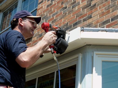
We trimmed the exterior of the bay with cellular PVC stock for durability and low maintenance, starting with the soffit and fascia. We also trimmed the windows with flat PVC stock. Where the windows met the house, we tucked the trim into the air space between the masonry veneer and the sheathing of the house. This left the unfinished back edge of the brick veneer exposed, so to finish the side trim, we caulked in standard brick mold between the brick and the window trim.
Finishing the roof
With the trim done, we turned to the roofing. We made all the flashings out of copper on a sheet metal brake—including drip edge, step flashing, and counterflashing—to match the copper flashing on the rest of the house. We made all the flashing for the roof from half of a 3-foot by 10-foot sheet of 16-ounce copper, which we purchased from a local supplier. Because copper is fairly expensive, I laid out the components to minimize waste. I marked the copper with a Sharpie for the layout, and then made a nick with aviation snips at each mark that served as a registration when positioning the material in the brake.
Step flashing for a conventional roof is usually 5 by 7 inches before being formed. But the bay roof shingles met the wall at an angle and needed longer pieces of flashing. So I formed lengths of copper and cut four pieces of step flashing 10 inches long from each one.
I form step flashing with an angle that’s slightly more than 90 degrees, so it springs in tightly between the roof and wall without interfering with the counterflashing. We also fabricated our own drip edge, customized to the project dimensions and to the correct roof pitch. To prevent galvanic reaction, we used copper roofing nails to fasten the drip edge and step flashing to the roof deck.
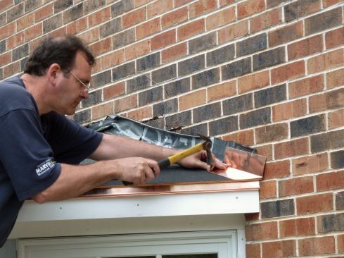
We installed roof shingles that matched those on the house and added counterflashing to cover the step flashing and the apron (see Saw-Cut Reglet Flashing illustration). In a perfect world, the counterflashing would go through the masonry veneer and under the WRB on the sheathing, but that would have meant tearing out and rebuilding the veneer (which was not in the budget). Instead, I let the flashing into the mortar joints two courses of brick above the roof in a stair-step pattern. I ground the mortar out of the joints to a depth of about one inch, using a mini-grinder fitted with a diamond blade. Then I laid out and sheared each piece, using a sheet-metal folding tool to bend the top leg 90 degrees to the body.
Starting at the low end of the roof, we installed the counterflashing by inserting the leg into the mortar joint. To hold the counterflashing in place, we made small rolls of scrap copper that we pushed into the mortar joints above the flashing. These “jelly rolls,” as they’re sometimes called, have enough spring in them to wedge the flashing in place. We make sure that these rolls are pushed in past the face of the brick so that they don’t interfere with the bead of sealant that finishes the joint. Progressing up the roof, each piece of counterflashing overlaps the one below it by a couple of inches.
To ensure a clean bond between the sealant and the masonry, I had rinsed the brick after grinding to remove dust and debris. After the brick had thoroughly dried, I applied a tripolymer sealant in a color that matched the mortar into each horizontal joint, sealing the flashing to the masonry. Vertical flashing joints were not sealed, to let any moisture behind the flashing escape.
The client insulated and finished the inside of the bay as part of an ongoing remodel. The bay took about three man-days to complete—longer than it takes to install most pre-manufactured units—but in the end the custom-fit bay was well worth the effort.
Veteran JLC Live Presenter Greg Burnet runs Chicago Window and Door Solutions, a carpentry contracting company in Chicago.