
In March 2018, four nor’easters blew through my home state of New Jersey. A client we occasionally hear from called and asked us to look at her deck, which had been hit by a large oak tree uprooted during one of those storms. It turned out that the damage resulting from the uprooted tree—which took out two sections of rail and damaged five joists —was the least of the deck’s problems; the rest of the deck was rotten to the core. Our client was lucky the tree hit the deck and revealed its other problems before someone was seriously hurt.
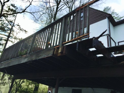
The original red-cedar deck sustained damage when a tree fell on it during a windstorm, but it was due for replacement anyway, thanks to sketchy ledger connection details and extensive rot.
When I assessed the damage for my client’s insurance company, I focused on the structural integrity of the deck as well as on the damaged area, since I didn’t want to be involved in a repair that might make us liable for the entire deck going forward. I thought it likely that the fallen tree had pushed the deck out of square, and that the deck returned to its original position only after the tree had been removed. Because I suspected that this may have compromised the joist-nail connections at the house ledger, in my proposal I provided an estimate for removing the existing deck and building a new one.
Demolition
Fortunately, our clients received their insurer’s OK for the full scope of work and gave us the go-ahead to get started. In New Jersey, permit application requirements vary from town to town, and even though we were not changing the deck’s footprint, the town required a copy of the survey showing the original deck’s location and an architect’s plan detailing deck construction. Two items we inherited from the existing deck were incorporated into the new plan: a 24-foot-long W10 cantilevered steel girder that supported the old deck framing, and an electrical service head attached to the southwest corner of the deck.
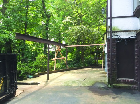
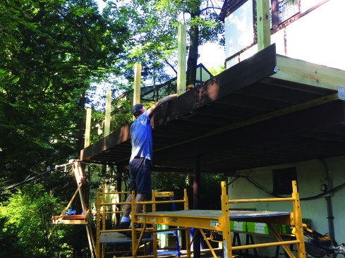
The columns and W10 steel girder supporting the deck were the only components that were reused. To stabilize the steel girder, the crew braced it with a 2-by and a cable tensioned by a come-along.
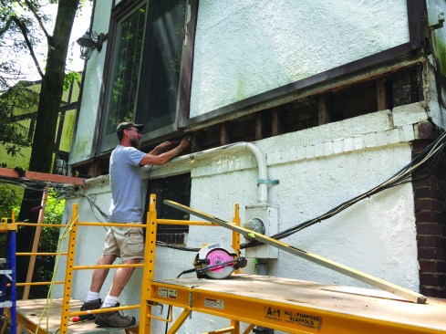
Because we weren’t sure how significant the load was where the cable came in contact with the deck, we supported the service head with a makeshift tripod, then attached it to the steel girder with a C-clamp and heavy-duty rope. Then we attached a cable and turnbuckle between the house and the girder (before attaching the service head), using an eyebolt through the foundation and another C-clamp on the beam. After that, demolition was a piece of cake.
Installing the Ledger
When project manager Danny DoCouto examined where the old ledger had been attached to the house, he determined that there was no rim joist to which we could bolt a new ledger. It also appeared that behind the house’s traditional three-coat stucco siding, a number of areas had rotted where the old deck ledger had been fastened. We had no choice but to remove the stucco siding down to the framing where the new ledger would be attached.
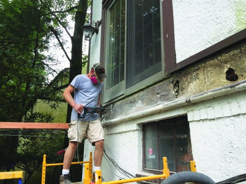
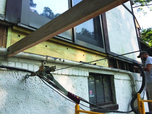
The stucco was cut away.
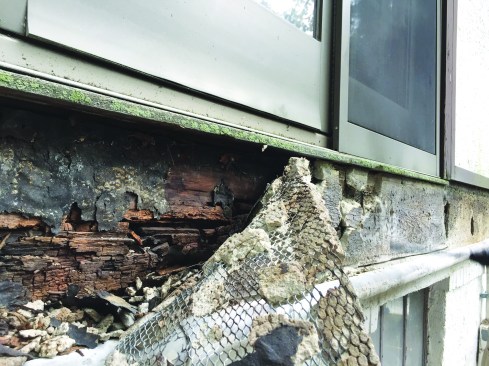
It revealed considerable damage to the sheathing …
… and the cripple studs underneath the sliding door.
To remove the stucco and the wire mesh, we cut through them with a grinder and chipping hammer, uncovering a balloon-framed system clad with rotted sheathing. Most of the cripples underneath the sliding door that provided access to the deck were rotted as well.
A solid PT header was installed underneath the slider to replace the cripples.
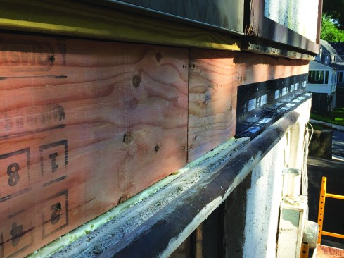
After resheathing, the crew flashed the assembly with Vycor.
We pulled off the rotted sheathing and removed the cripples, but rather than replacing them, Danny used treated 2x10s to build up a solid header under the sliders. Where the framing was exposed, we pulled out the old fiberglass insulation and filled the bays with Rockwool Roxul stone-wool insulation to provide a fire stop and some protection from air infiltration. Then we installed new 1/2‑inch sheathing to complete the rebuild, giving us a sound substrate for the new ledger.
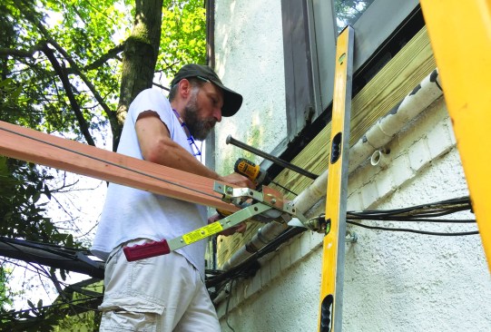
The crew installed a new ledger.
The new ledger was lag-bolted to the house framing.
After marking the stud locations on the stucco siding, we covered the sheathing with two strips of 12-inch-wide Vycor SAF flashing. We installed the lower strip first, taking care to lap it over the stucco at the bottom. When we installed the upper strip, we tucked the flashing in as best we could underneath the membrane behind the stucco at the top and made sure it lapped over the bottom strip. Then we bolted the ledger into place directly into the studs and the header underneath the sliders.
Out-of-Level Girder
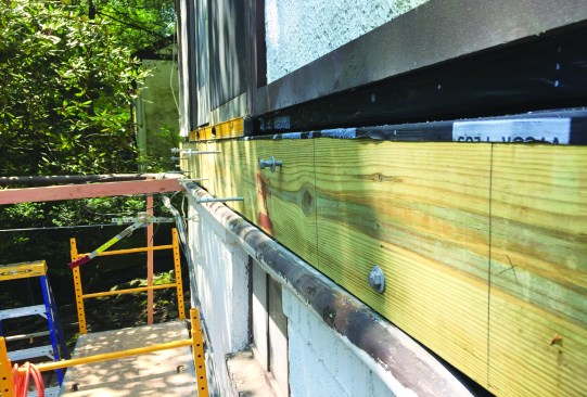
The old girder was primed, painted, and capped with a flashing membrane and a treated 2×6 plate.
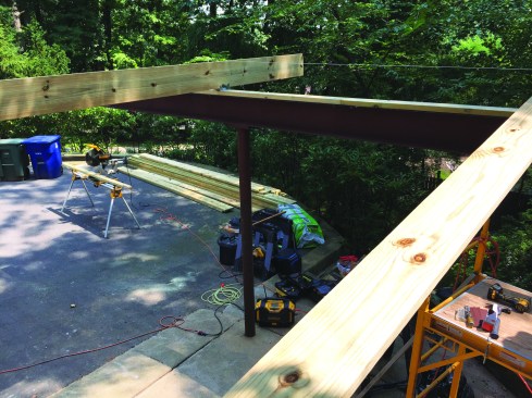
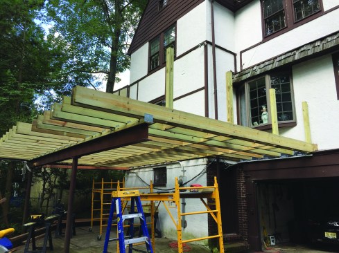
Next, we tackled the 24-foot-long W10 girder, which was cantilevered 8 feet on the driveway side so no obstruction interfered with the access to the three-car garage. We were concerned that it had been compromised, since its cantilevered side had been hit when the oak tree came down on the deck. An engineer who the homeowner had consulted on the project approved it for construction and provided documentation to include in our permit application stating that the existing girder could safely support the proposed loads.
A string line established a reference elevation for the out-of-level girder.
Still, when we checked elevations on the girder and house with a laser level, we discovered that the girder was 2 3/4 inches out of level. Whether the impact of the tree had bent the beam or fatigue was a factor (or both), others who were higher up the food chain had approved the girder for construction. So rather than continuing to speculate, we concentrated on a solution for installing joists on the out-of-level girder.
After scraping and priming the girder, we applied Vycor flashing tape to the top of the beam and bolted a PT 2×6 plate in place. We placed the first joist on the high side of the girder, where the joist was dead level. Because we wanted to pitch the framing slightly from the ledger to the outside edge of the deck, we notched the 2×6 plate with a circular saw and chisel so that the joist was recessed into the plate by 1/2 inch.
Next, we installed a second joist 16 feet away from the first, where the girder started its cantilever. This joist required a 1-inch-thick shim instead of a notch to maintain the same pitch. We then pulled a line between the two joists, so that we could set the remaining joists with the line dictating how much shimming or notching would be required to bring each joist up to level.
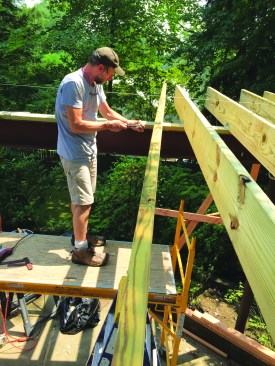
Notches or shims were used as needed.
The joists are leveled flush with the string.
To match the string height, we ended up recessing the first four joists, while the next two were installed flush with the plate. We had to shim the next six joists. Finally, before installing the last joists on the cantilevered portion of the girder, we screwed a 5/4-by-6-inch treated board to the 2×6 girder plate to reduce the size of the shim needed under each joist. Then we shimmed the final joists to their proper height, using a 6-foot level for reference.
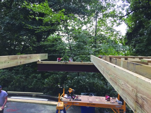
Here, the deck is almost completed.
Once we’d taken care of the problems with the ledger and the beam, the rest of the deck installation went smoothly.
Photos by Rob Corbo