Giant Screws
Pier design varies according to soil conditions and loading requirements. Each steel pier consists of a lead section with one to four helical bearing plates that thread into the soil with minimal disruption, like a giant wood screw. The lead section pulls plain square shaft sections — which are bolted on in sequence — behind it. The last embedded shaft is cut to the desired height above grade and capped by a flat 8-inch-by-8-inch steel bearing plate, which is welded in place. The plate transfers the structural load to the pier.
For this job, we used “8-10-12” triple-helix lead sections (the numbers refer to the successive diameters of the three bearing plates) and a 1 3/4-inch-square shaft. Shaft sizes range from 1 1/4 to 2 1/4 inches square.
Concrete grout is used in certain helical-pier installations to increase lateral friction and thereby gain additional bearing capacity from an otherwise slender steel column. Grouting also helps protect the hot-dipped galvanized steel from corrosive soil; on this project, where salt posed a concern, grout was specified.
Giant Screwdriver
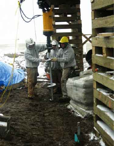
The auger attached to the arm of our track excavator is basically a giant hydraulic screwdriver, capable of producing 12.5 kips (12,500 pounds-force). We first turn the lead section into the ground to its full 5-foot depth, then attach a proprietary displacement plate to the shaft. When rotated, the displacement plate thrusts the soil aside to create a grouting cavity around the shaft.
Friction-fitted to the digging plate is a 4-foot length of 6-inch-diameter PVC casing. The casing is pressed down along with the next shaft length until it’s just about flush with the grade, and becomes a reservoir for introducing grout as shaft sections are added. We use a 2-to-1 sand mix with Type II cement and just enough water to make the grout flow. The grout is pulled downward by gravity and the square shaft’s rotation, following the digging plate to eventually encase the entire length of the pier above the lead section.
Monitoring torque. There are a few accepted ways to determine when you have reached the pier’s designed capacity. The method we use is the most precise, relying on a computerized torque indicator that delivers a constant readout of the hydraulic pressure delivered to the auger as it turns the shaft. We mark each shaft section at 1-foot intervals and record the readout as each mark reaches grade level.
While the engineer’s design documents required us to submit for approval a complete record for each pier, an engineer was also on site during the first few installations to verify the field conditions and results.
Grade Beam
The reinforced-concrete grade beam — which looks just like a footing — is essentially a structural header spanning from one pier to another, providing full support to the building. We shoveled a shallow trench for the 30-inch-by-16-inch beam, then placed the prescribed rebar. There’s no need to dig in below the frost line since the beam rides on the piers, not on grade.
On top of each pier’s bearing plate, we welded four #4 upright “dowels” with 10-inch horizontal legs to tie in the stem wall. This ensured full continuity from the bottom of the pier to the top of the foundation. We set similar dowels on 16-inch centers along the entire length of the beam for tying in horizontal rebar.
With the rebar tied and the beam formed, we pumped a 4,000-psi, 3/4-inch aggregate mix in from the street — about 90 feet away — using the excavator arm to direct the pump hose. We keyed the top of the beam to receive the 3-foot-4-inch-high stem wall, which we formed the following day. We set pressure-treated wood bucks inside the forms for the stainless steel Smart Vents (877/441-8368, www.smartvent.com), which will allow floodwater movement but exclude critters.
It took us two-and-a-half days to install a total of 21 piers, at an approximate cost of $1,500 per pier. It took another week to tie the rebar, and form and pour the beam and walls. With the first-floor framing replaced and the entire structure unified with wind-resistant metal connectors, this house should stand for a long time to come.
Fred Ambrose is president of Ambrose Homes in Chatham, Mass.