Joist Depth
Rule of thumb. Most codes assume residential floor loads to be 50 pounds per sq. ft. — 40 pounds live load plus 10 pounds dead load. If load conditions do not exceed this value, you can use the following rule of thumb for sizing uniformly loaded residential floor joists:
Half the Span + 2 = Joist Depth
First, round the clear span of the floor joist up to the nearest foot and divide by 2. Then add 2 to the answer. For example: For a clear span of 15 ft. 6 in., round up to 16 and divide this span by 2, giving you 8. Next, add 2 to get the required depth in inches (8 + 2 = 10). It’s important to use the actual lumber dimensions, not the nominal dimensions, so a 2×12 floor joist will be required.
Design Loads for Floor Joists
Live loads. A 40-psf live load will meet most codes for residential living spaces (some require only 30 psf in bedrooms). For typical live loads, see figure below.
Figure: Live Loads for Floors and Ceilings
| Component | Live Load (lbs./sq. ft.) |
|---|---|
| Residential rooms | 40 |
| Decks | 40 |
| Balconies | 40 |
| Fire escapes | 40 |
| Stairs | 40 |
| Ceiling joists (limited attic storage) | 20 |
| Ceiling joists (no attic storage) | 10 |
Dead loads. For dead loads, 10 psf is adequate for standard wood-frame construction. For mortar-set ceramic tile floors, frame for a 20-psf dead load. For other special situations, calculate loads based on weights of building materials (below).
Joist Spacing
Floor and ceiling joists are typically framed 24, 19.2 or 16 in. o.c. The 16 in. o.c. provides a stiffer floor. They may be also framed at 12 in. o.c. to further increase stiffness, or to increase the span in one section of a floor system without changing lumber depth.
Joist Span
Joist span means the clear, horizontal distance measured between the center of bearing to the center of bearing . (below).
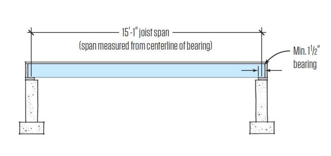
Span is measured from the center of bearing to the center of bearing.
The actual joist length is longer to provide bearing at each end. Spans for dimensional lumber floor and ceiling joists can be calculated using the American Wood Council’s Maximum Span Calculator for Wood Joists and Rafters.
Framing Details
Sill Plates
For sill plates in contact with concrete or masonry foundations, use pressure-treated wood to protect against decay and insect attack. Naturally decay resistant species, such as redwood, cedar, black locust and black walnut, are also allowed.
Anchor Bolts
Bolt the sill plate to the foundation with anchor bolts or strap anchors spaced no more than 6 ft. apart.
Most codes call for minimum 1/2-in. steel J-bolts embedded at least 7 in. in concrete, mortar joints, or solid-grouted masonry units. Each section of sill must have at least two bolts, with one bolt placed somewhere between 3 1/2 to 12 in. from each end (below). Each bolt needs a nut and adequately sized washer.
Wedge anchors. If anchor bolts are missing, use 1/2-in. wedge anchors or adhesive anchors. With a wedge anchor, tightening the nut expands the anchor until it’s locked tight against the sides of the hole. A wedge anchor must be tightened to the manufacturer’s specified torque. Tightening it too much can pulverize the surrounding concrete. Also, anchors can’t be placed too close to the edge of a concrete slab or foundation wall.
Adhesive anchors. Adhesive anchors can be spaced closer to each other, and closer to the edge of a slab or wall, than wedge anchors. Follow the anchor manufacturer’s recommendations for placement, spacing and depth.
Joist Bearing
Joists should have at least 11/2 in. of good bearing on wood or metal, or 3 in. on masonry or concrte. If necessary, you can safely notch a joist at its bearing point up to one-fourth the depth of the joist.
Boring and Notching Joists
In general, do not make any notches in the middle third of a joist. Also, avoid vertical cuts in the bottom of a joist; angle the cuts instead to reduce the likelihood of splitting.
For safe placement of holes or notches in other parts of the joist, follow the guidelines in the figure below.
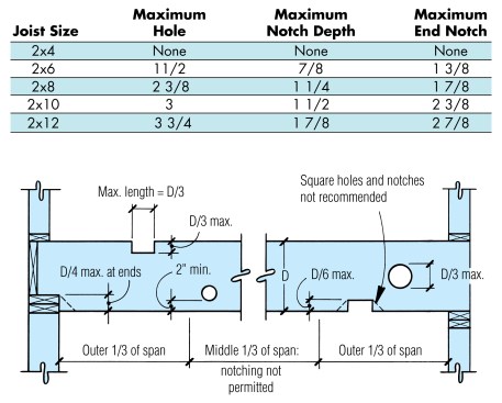
Do not notch a span’s middle third where bending forces are greatest. For all calculations, use actual, not nominal, dimensions.
Metal ties are needed when a hole or notch removes more than 50% of a wall plate. Where mechanicals need to pass through a joist supporting a partition, double the joist with blocking in between to create a cavity (below).
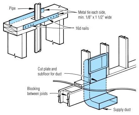
Top: Metal strap ties are required when more than 50% of the plate has been removed. They are not required on the side of a wall that is fully sheathed with wood structural panels. Above: Joists supporting partitions should not be cut or notched to accommodate mechanicals. Instead, double the joist with blocking in between to create a cavity.
Rim Joists and Bridging
To prevent joists from twisting, the ends must be nailed to a solid band joist (rim joist) or header. If there is no band joist or header, nail solid blocking between the joist ends. Most codes don’t require additional bridging unless the joist is larger than a 2×12, in which case bridging is needed every 8 ft. However, solid or X-type bridging at mid-span will help stiffen any floor.
Load Paths
All loads start at the roof and must transfer on an unbroken path through structural elements to the foundation. Many cracking problems, which are misinterpreted as “settling,” are actually caused by broken load paths. These broken paths result in loads being carried by areas that were not designed to carry them.
Support for Loadbearing Walls
Parallel to joists. Ideally, if a loadbearing wall runs parallel to the floor joists, then it should sit directly over a beam or a joist supported by a loadbearing wall below. If the loadbearing wall sits between two joists, complete the load path by installing solid blocking between the two joists every 16 in. o.c.
Perpendicular to joists. If a loadbearing wall runs perpendicular to the floor joists, it should be offset from a supporting beam or loadbearing wall below by no more than the depth of the joists (below).
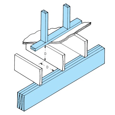
Never offset a loadbearing wall from a beam or loadbearing wall below by more than the depth of the joists.
Support for Non-Loadbearing Walls
A non-loadbearing wall that runs parallel to the joists doesn’t need to be placed directly over a joist. However, when it’s not directly over a joist, solid blocking should be installed between the joists to carry the load (below). If the wall is placed directly over a joist, that joist should be doubled.
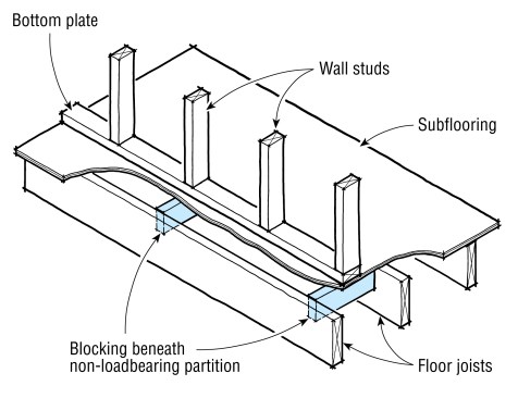
Install blocking where a non-loadbearing wall rests between two joists. Where it rests directly on a joist, the joist should be doubled.
Point Loads
A concentrated load that bears on a floor system — such as a structural post — must sit directly over a post or beam below. In addition, solid blocking (with a cross-section at least as large as the post) must carry the load through the floor system to the underlying post or beam.
Floor Openings
Where a floor opening is more than 4 ft. wide, both the headers and trimmers should be doubled (below). Headers over 6 ft. long must be fastened with steel connectors and should be sized according to the load.
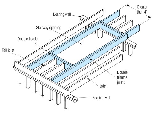
Where a header in a floor opening exceeds 4 ft., double the headers and trimmers. Where the header exceeds 6 ft., it should be installed with framing anchors.
A tail joist in a framed opening that’s over 12 ft. long should be connected with hangers. Otherwise, it should sit on a 2×2 (min.) ledger nailed to the face of the header.