
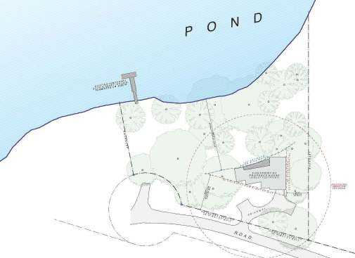
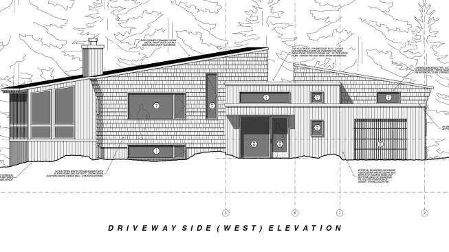
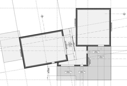
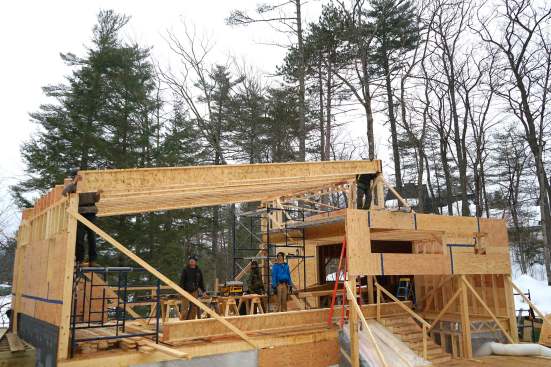
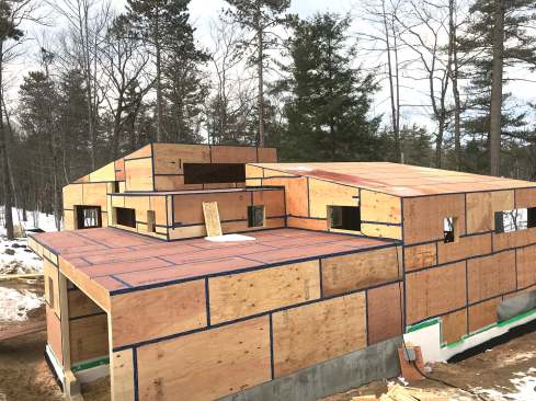
When architect Eric Sokol (Winkelmann Architecture, Portland, Maine) took on the challenge of squeezing a high-end custom home into the pie-shaped buildable outline of a wooded lakeside lot in ski country, he solved the problem using every trick in the book. A split-level entry on the road side of the house gives access to a wide-open downstairs living and entertainment space with exposed wood ceiling beams, offering a private view of the water. Upstairs, a pair of shed-roofed spaces set at a ten-degree angle to one another, and connected by a flat-roofed entry, form the shell for a master bedroom suite at one end of the house and an open-plan living, dining, and kitchen area at the other end — all while allowing the entire building to nestle comfortably into the rustic setting.
To frame the complex forms of this modern design, architect Sokol and engineer Albert Putnam specified a smorgasbord of structural components tailored to manage the long spans and point loads involved: steel I-beams, heavy glue-laminated timbers, built-up laminated veneer lumber (LVL) girders, custom angled steel connectors, trimmable-end web-truss floor joists, and wood I-joist roof rafters.
“No two projects are the same,” Putnam told JLC in an email. “We start with cheap and easy and crank it up as required. There are lots of details in this one… flush headers (no room for dropped headers), lift slide doors (allowable header deflection 1/16″… hence the steel), cantilevers, offset geometry, exposed structural framing, super-deep framing requirement for insulation cavities, very high snow load, et cetera, et cetera.”
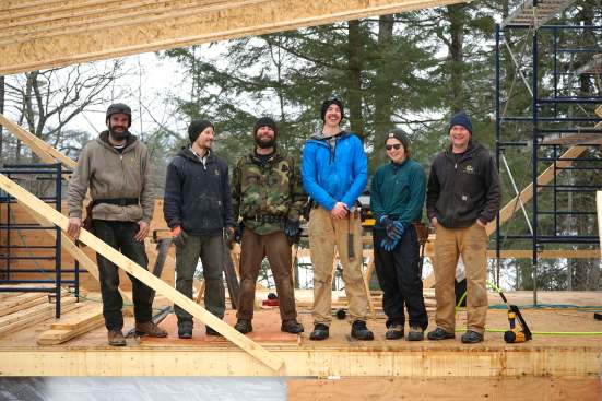
Sokol and Putnam’s complex structural assembly posed a construction challenge to Maine builder Jesper Kruse, owner of Maine Passive House, and his crew of skilled carpenters. This winter, JLC spent a few days on the job site with the Maine Passive House team to see how they put the puzzle together. Check out our slideshows on this page, starting with the foundation and first floor framing.
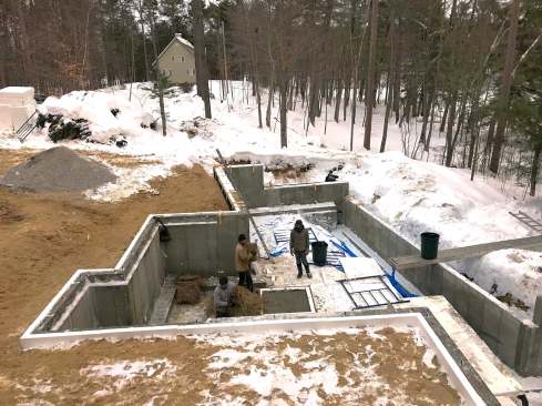
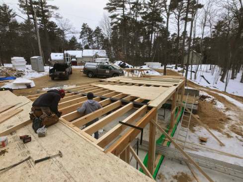
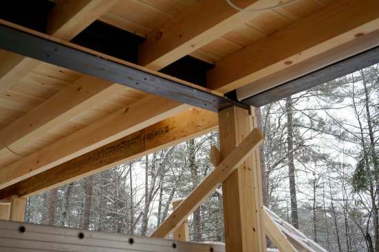
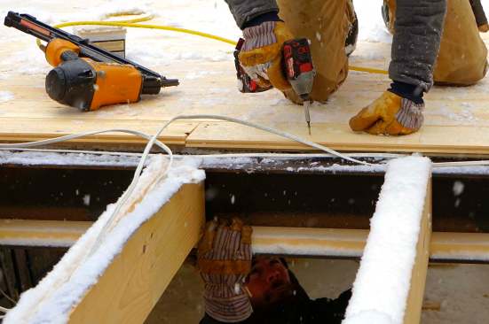
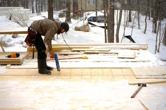
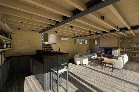
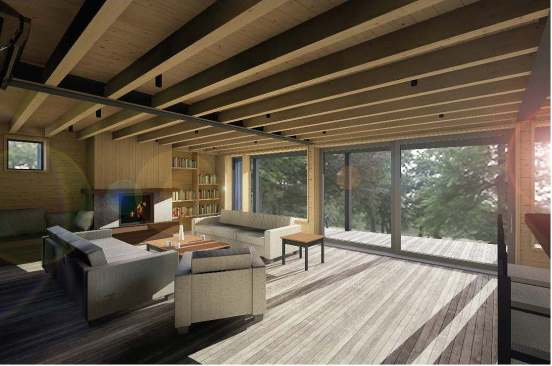
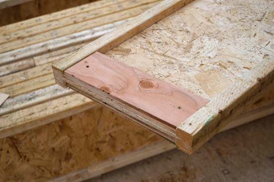
The lower level living space (slideshow left) opens onto a view of the woods and the pond. Sokol designed an open entertainment space with a bar, fireplace, and bookshelves, with exposed sawn lumber beams in the ceiling supported by a steel I-beam. To frame the structure for this space, the crew had to set the steel I-beam first, then install the sawn beams (seated on the bottom flange of the steel beam, notched out around its top flange, and routed on the top face to accept wiring that would power ceiling lighting fixtures in the room below). Then the crew applied tongue-and-groove ceiling boards, topped by Advantech subflooring — thus installing the finish ceiling for the downstairs gathering room at the same time as they framed the floor for the upstairs living area.
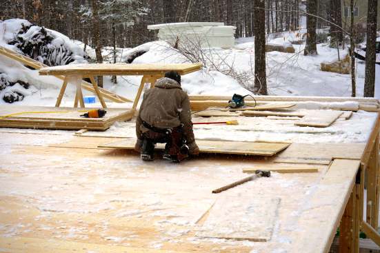
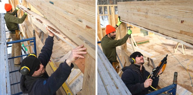
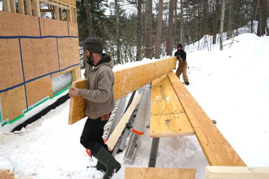
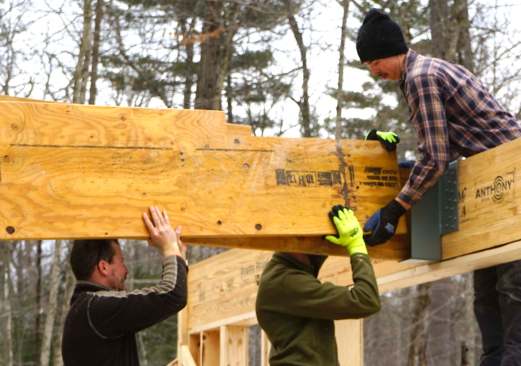
The front wall for the home’s split-level entry has a broad window facing the road. But that wall also catches the end of a massive carrying timber, running from front to back through the structure. The heavy girder holds up two roofs: the beam carries one end of the rafters for the flat-roofed center of the house, and it also supports one end of wood I-joist rafters that span 28 feet at a 2:12 pitch, forming the shed roof for the upper-story open-plan living room and kitchen. To support the point load of the beam end, the header across the front-facing window had to be a serious piece of wood: engineer Putnam called for a Power Beam glue-laminated timber from Anthony Forest Products, at 5.5 inches wide and 16 inches deep — which the crew muscled into place on the wall without benefit of heavy equipment.
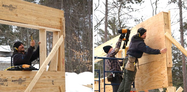
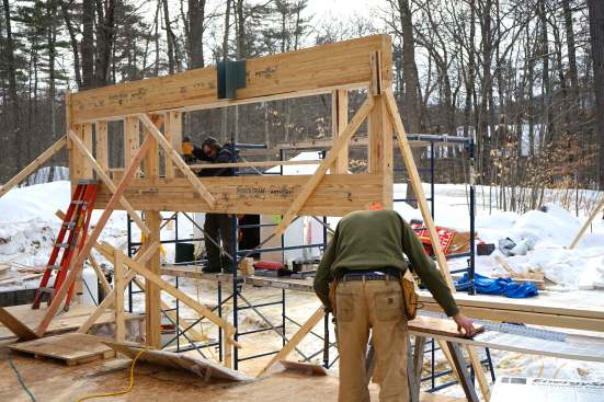
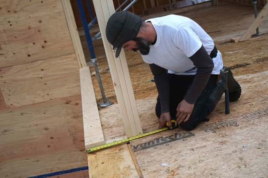
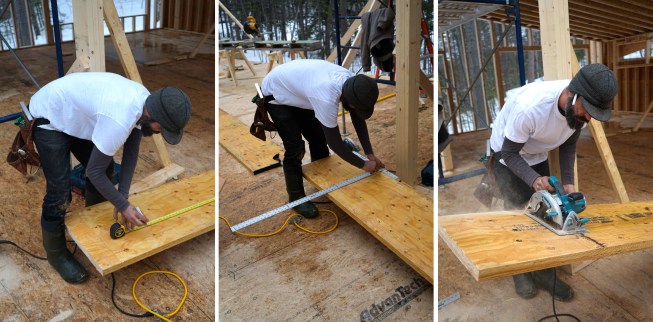
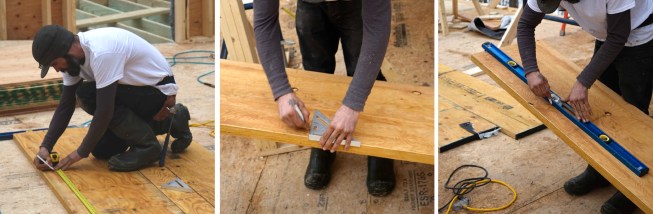
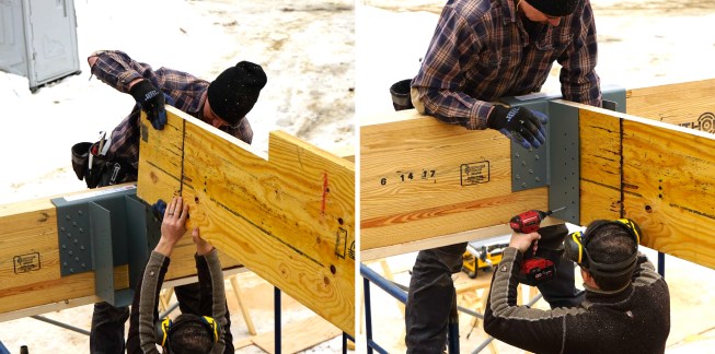
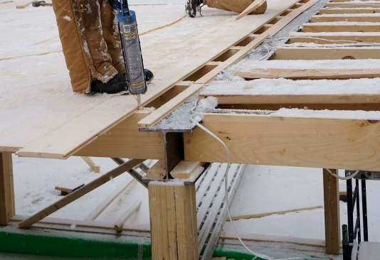
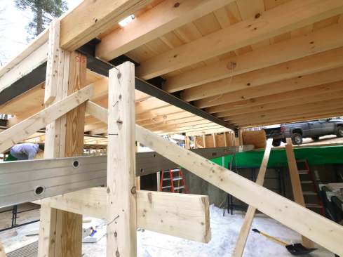
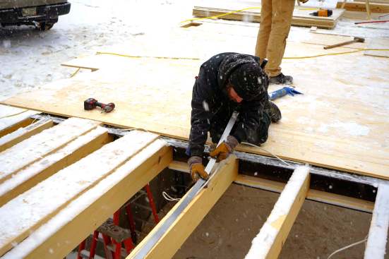
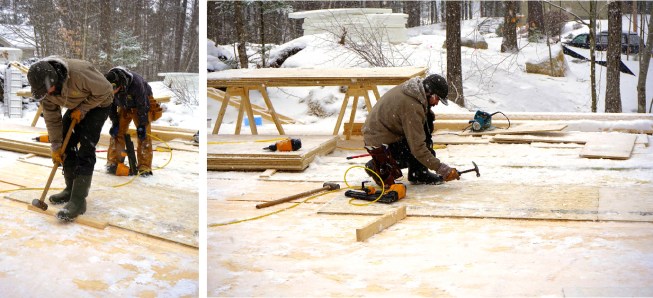
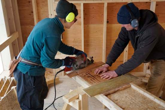
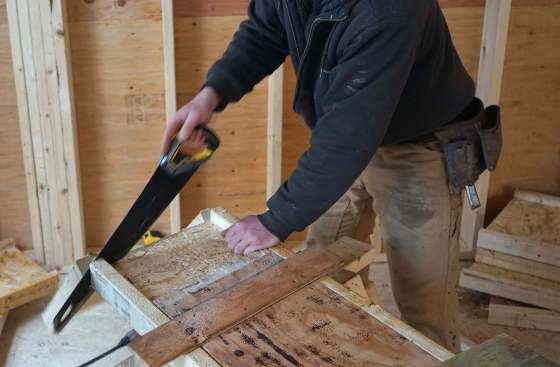
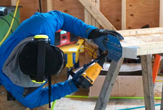
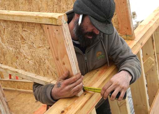
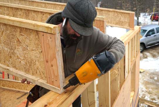
Carpenters mark, measure, cut, and place 20-inch LVL members as …
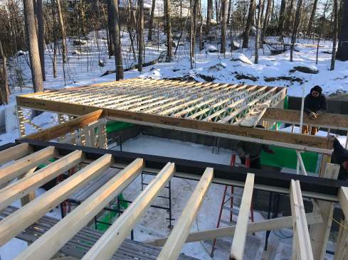
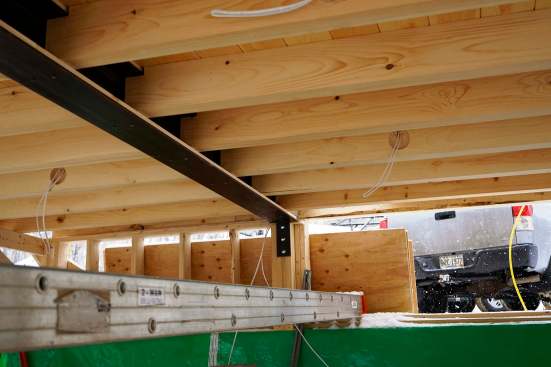
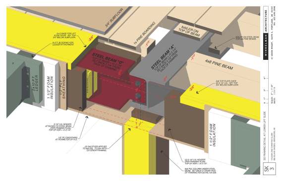
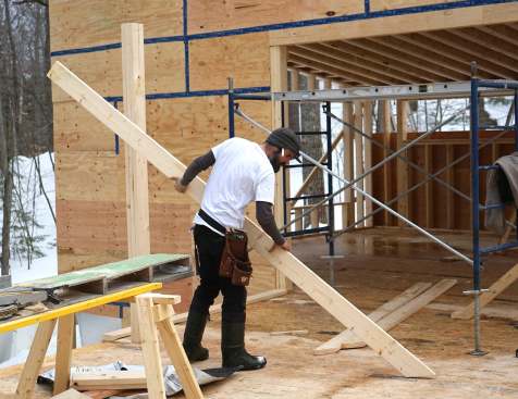
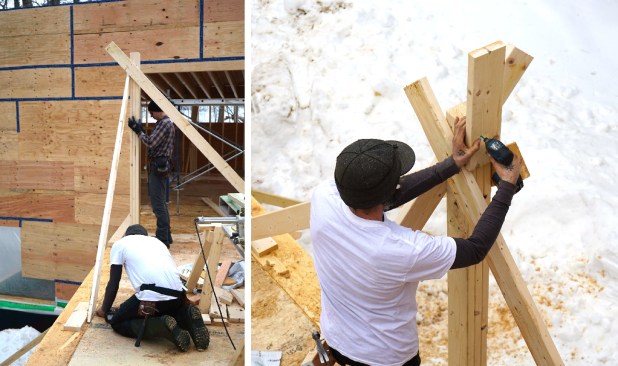
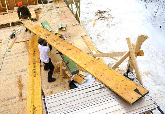
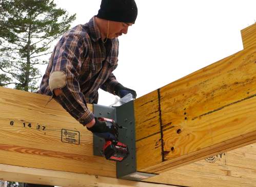
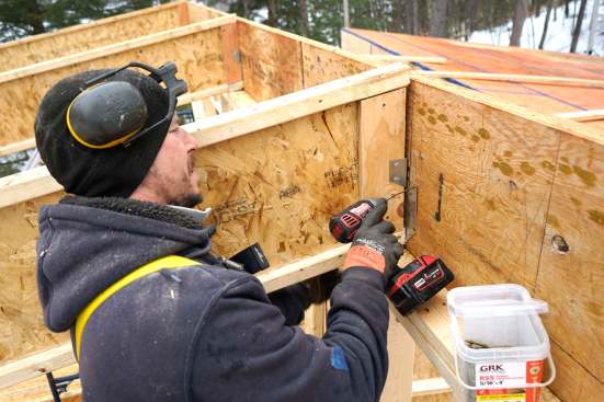
To fit the pie-shaped buildable area of the lot, the two wings of the home’s upstairs meet at a 10-degree angle — which means that the main LVL carrying timber of the living space roof meets the front-wall glue-lam at that same angle. Kruse’s crew had to make that connection with a custom steel connector, bolted into the glue-lam using self-tapping structural bolts. Then the carpenters had to assemble the big carrying timber out of three 1-7/8″ by 20-inch LVLs, each cut on the 10-degree bevel to the correct length, and placed into the connector by hand (see slideshow).
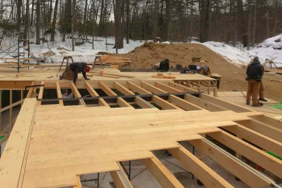
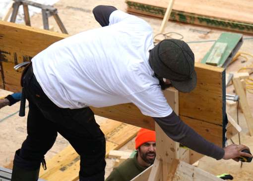
The massive built-up LVL beam directly supports the flat roof of the home’s center section. Above it sits an upper wall with a long window, topped by another beam (just one LVL this time). The upper LVL receives the top end of the shed roof’s wood I-joist rafters, which span 28 feet over the home’s open-plan kitchen, living room, and dining room.
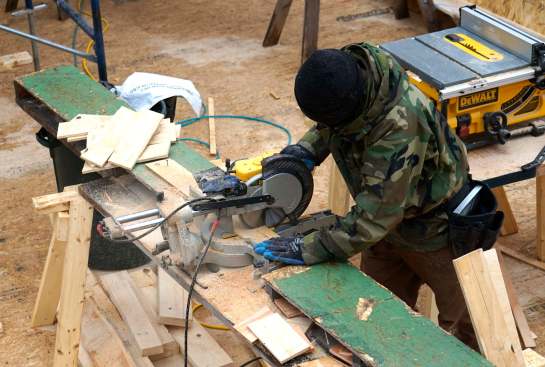

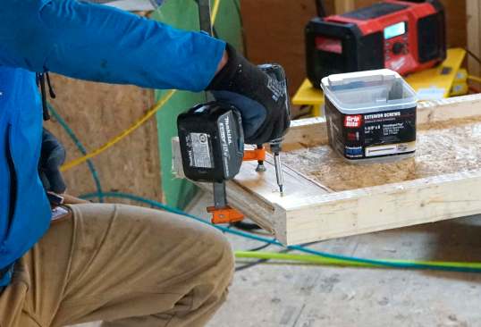
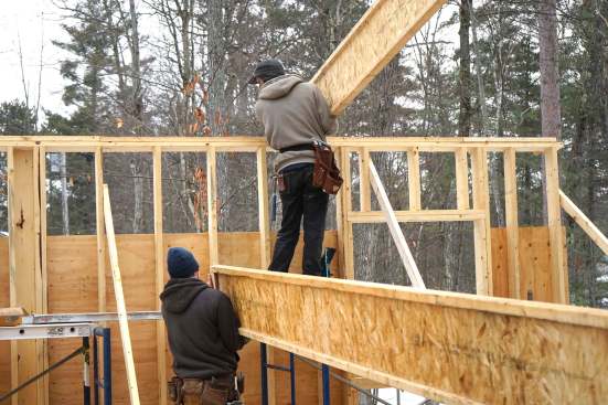
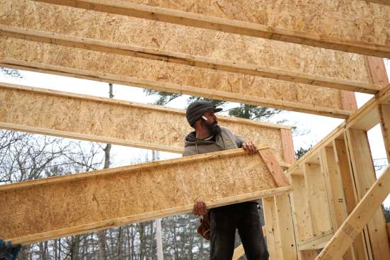
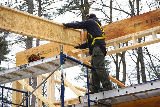
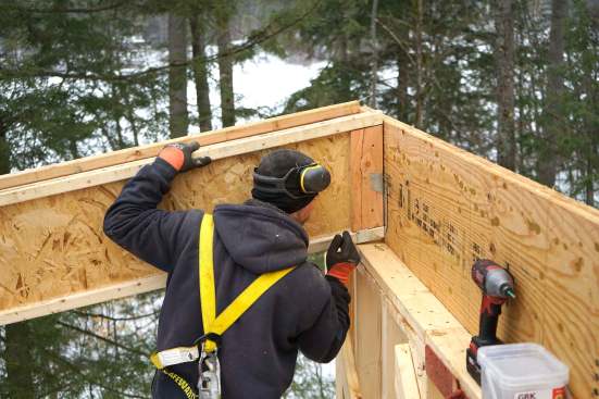
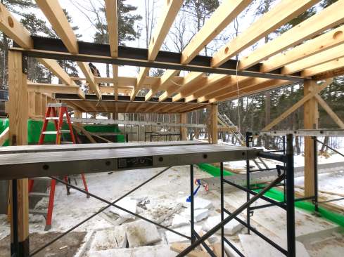
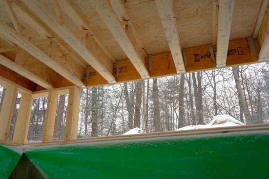
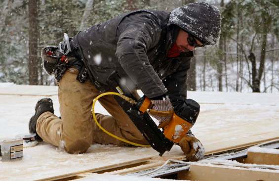
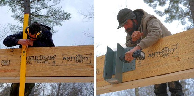
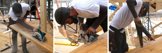
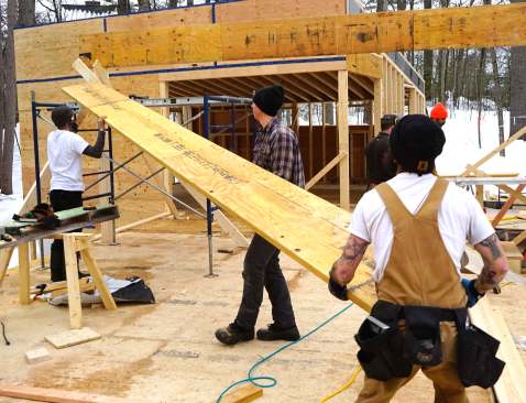
The crew frames a long span.
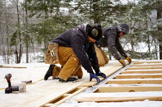
The crew angled the top cuts on the studs for the wall that supports the lower end of this long roof span, creating a beveled top plate for the wall, so that the wood I-joists could sit flat on the plate. At the top, where the rafters dead-end into the LVL rim joist (which is also the window header), the wood I-joists were fastened using angled Simpson joist hangers. The crew worked assembly-line fashion to ready the wood I-joists for installation: cutting the rafters to length, cutting angled web stiffeners for the rafter ends, attaching the joist hangers at the top end of the rafters, and passing each rafter up to carpenters Matt Friel and Alex Strugatskiy on the staging at the two supporting walls.