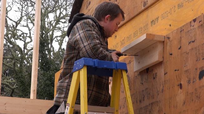
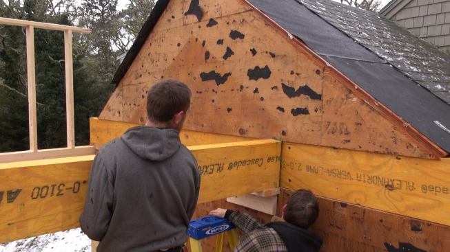
Carpenter Russ Laffin sets a temporary shelf to catch the end of…
Carpenter Russ Laffin sets a temporary shelf to catch the end of a built-up two-ply LVL beam for the floor frame of a second-story loft under the cathedral ceiling of a high-performance addition on Cape Cod.
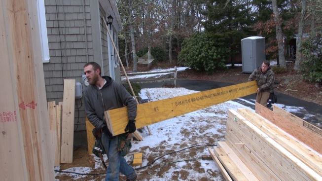
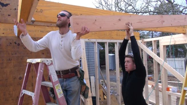
Mike Hill and Russ Laffin carry the main girder for the loft flo…
Mike Hill and Russ Laffin carry the main girder for the loft floor frame into the addition.
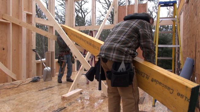
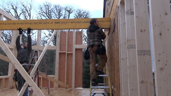
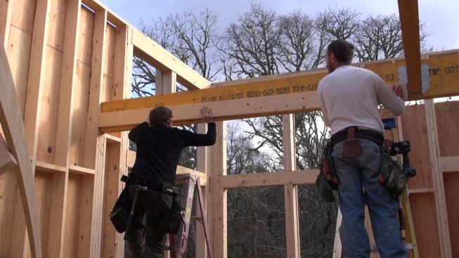
Maneuvering the heavy beam between temporary wall braces, Hill a…
Maneuvering the heavy beam between temporary wall braces, Hill and Laffin prepare to set the end of the beam onto the post built into the wall at the left of the photo.
The carpenters set the end of the beam onto the temporary shelf,…
The carpenters set the end of the beam onto the temporary shelf, before securing it to the beam already embedded into the wall of the existing house.
Laffin positions the beam, sliding it along the temporary shelf.
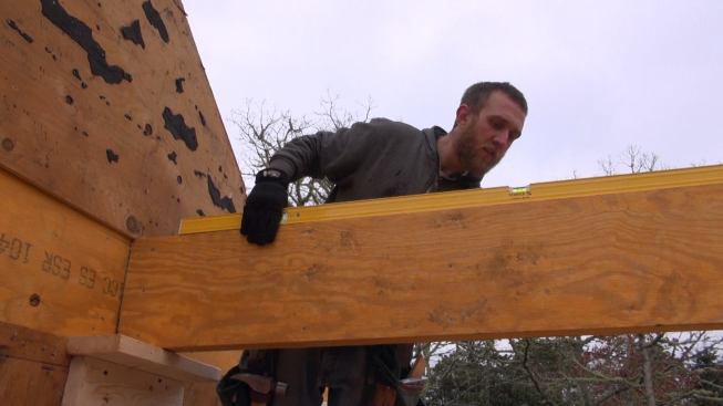
Hill checks the floor beam for level.
Hill drives a temporary support post into position under the bea…
Hill drives a temporary support post into position under the beam, so he can remove the temporary shelf from the wall under the beam and install a permanent Simpson structural hanger.
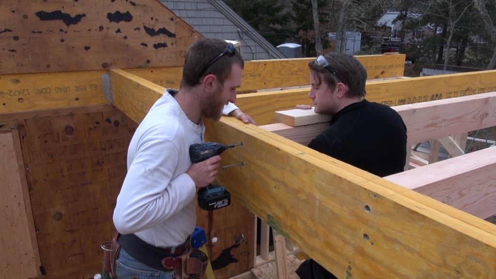
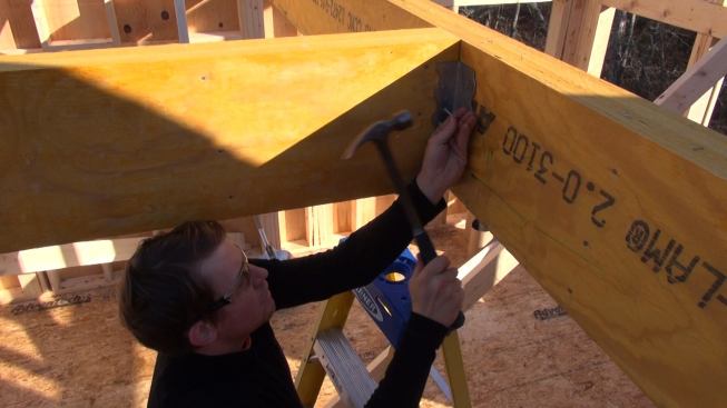
Laffin drives nails into the structural hanger to make the perma…
Laffin drives nails into the structural hanger to make the permanent connection between the LVL beams.
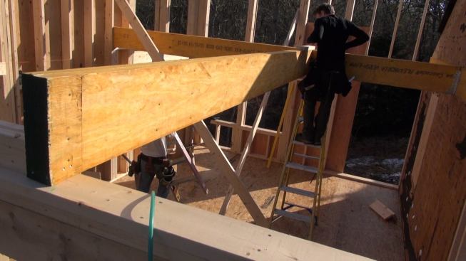
Laffin and Hill set the next beam for the floor system, which de…
Laffin and Hill set the next beam for the floor system, which defines the stair opening. Where this beam meets the main beam, a temporary scab screwed into the top of the new beam holds the two beams flush at the top. The near end of the beam sits atop a double two-by-four buildup of the outside wall of the addition.
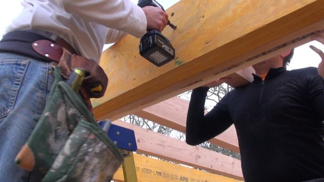
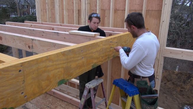
Hill drives six-inch FastenMaster structural screws to connect t…
Hill drives six-inch FastenMaster structural screws to connect the two double-LVL beams together and pull the connection snug. Next, this joint will be secured with another Simpson steel connector.
Laffin nails off the Simpson connector to the LVL beam joint.
Preparing to fill in the floor framing, Hill and Laffin set a te…
Preparing to fill in the floor framing, Hill and Laffin set a temporary 2×6 ledger board to catch the ends of the 4×8 Doug Fir floor joists for the loft floor frame.
Hill and Laffin set a Doug Fir 4×8 floor joist in place.
Not wanting to take a chance on splitting the end of the expensi…
Not wanting to take a chance on splitting the end of the expensive lumber, Hill drills a pilot hole in the outboard end of the Doug Fir joist. The cut ends of the joists, graded Select Structural, show 15 to 30 annual growth rings.
Hill drives a countersunk FastenMaster structural screw to make …
Hill drives a countersunk FastenMaster structural screw to make the connection between the Doug Fir joists and the LVL main beam. Later, the connection will be beefed up with a Simpson joist hanger.
Hill sets the screws for another joist while Laffin holds the fl…
Hill sets the screws for another joist while Laffin holds the floor joist to its layout line.
Earlier this month, Coastal Connection spent a day on site on Cape Cod, Massachusetts as local contractor Mike Hill framed the walls for a walk-out basement room at the lowest level of a new addition. This week we’re back on the job as Hill and carpenter Russ Laffin work on the upper story of the addition.
Hill is the framing sub on this this job, working for builder and remodeler Mike Horgan. Here, Hil and Laffin are framing in the floor structure for a second-story loft (see slideshow), starting with an LVL main beam system to define the loft floor and the stair opening, then filling in with 4×8 Doug Fir joists. Connections for the floor are made with 6-inch FastenMaster structural screws and Simpson steel connectors.
Once decked, the loft will serve as a platform for pipe staging, which Hill will use to set the building’s LVL structural ridge and I-joist cathedral roof. Then, Horgan will be back on the job to help with construction of the airtight exterior membrane, which will extend all the way up the building’s exterior walls and continue up onto the plane of the roof.