Lumber grade and species. Because we were imitating local carpentry details, we used pressure-treated (ACQ or CA-B) 2×8 southern pine to simulate the joists and No. 2 southern pine 4×4 posts. Some of the tests included a PPT 5/4×6 radius-edge deck board attached to the joists and band joist. We bought the lumber in “wet” condition (moisture content greater than 19 percent) and kept it that way before the test so that we wouldn’t have to apply an adjustment factor for “wet use” to our test data.


The authors first tested two post connections found commonly in …
Test Results
We tested five samples each of the bolted and lag-screwed post connections. What became obvious is that these standard details don’t come close to meeting the code load requirement.
Test Results: Lag Screws and Bolts | ||||
Post-to-Deck Connection Assembly | Average Test Load (lb.) | Range of Test Loads (lb.) | Average Deflection at 200 lb. (in.) | Average Test Load as Percentage of 500 lb.* |
1/2-inch Lag Screws | 178 | 146 to 211 | NA | 35% |
1/2-inch Bolts | 237 | 217 to 248 | 4.4 | 47% |
*Must be greater than 100 percent to be considered code-conforming | ||||
The lag-screwed connection failed at less than 200 pounds when the lags pulled out of the band joist. The bolted connections failed at an average load of 237 pounds — barely surpassing the code design load but with almost no safety factor for the service life of the deck. The bolted samples typically failed when the band joist peeled away from the deck joists, as the screws attaching the band to the joists pulled out. The screws holding the 5/4 deck board to the joists and band joist failed early in the tests.
Once it was clear these two common details were inadequate, we tried various ways of blocking around the post, attempting to distribute the load over many lag screws to reach the 500-pound test load. These attempts typically failed when the lumber split under perpendicular-to-grain loading — the kind of load exerted when you split wood with an axe.
A Different Approach
As the testing progressed, we realized that the high forces at the base of the post were not going to be resisted by fasteners loaded in withdrawal or by blocking loaded perpendicular to the grain. What we needed was a way to arrange the bolts so that the load from the post to the joist would be transferred in shear (lateral loading), because bolted connections are very strong when handling lateral, or shearing, loads.
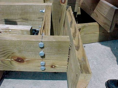
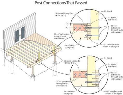
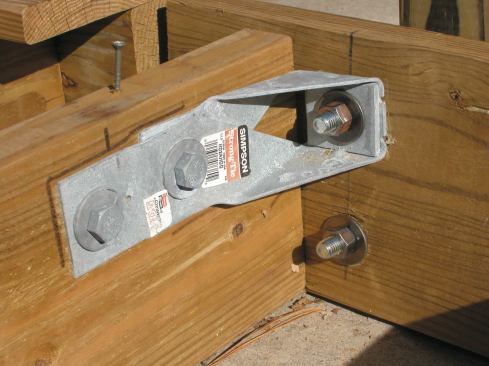
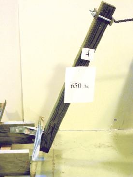
We turned to a commercial steel connector — a Simpson Strong-Tie HD2A — which is designed to resist wind and earthquake loads in shear walls. By orienting the connector sideways along the joist, we were able to use it to secure the post. We installed the HD2A with three 1/2-inch-diameter bolts: The two bolts in the joist are loaded in shear, while the third bolt, passing through the post, the band, and the connector itself, is loaded in tension. As part of the tested design, we also installed another 1/2-inch bolt in the lower part of the post and the band joist. We applied at least 650 pounds to the top of the post; every specimen successfully resisted the load.
We tested the connection two ways — with the post located inside the band and on the outside. We observed different types of failure for the two cases as the load increased up to the maximum of about 650 pounds.
Test Results: HD2A Anchors | ||||
Post-to-Deck ConnectionAssembly | Average Test Load (lb.) | Range of Test Loads (lb.) | Average Deflection at 200 lb. (in.) | Average Test Load as Percentage of 500 lb.* |
HD2A Anchor (4×4 post inside band) | 645 | 593 to 687** |
| 129% |
HD2A Anchor (4×4 post outside band) | 686 | 653 to 713** | 1.9 | 137% |
* Must be greater than 100 percent to be considered code-conforming **Tests stopped to protect test equipment | ||||
When the post was mounted inside the band, the washers under the bolt head embedded into the wide face of the 2×8 band joist. When the post was located outside the band, the bolt head and washer pulled well into the 4×4 post, crushing the wood fibers beneath the washer.
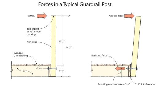
We used only one Simpson HD2A per post, placing the centerline of the connector 2 inches below the top edge of the 2×8 joist. If you use this detail in the field, it’s important to maintain this centerline distance, because it helps to limit the forces involved in the connection. If you place the HD2A lower, you’re reducing the resisting lever arm, which extends from the bottom of the band joist to the centerline of the connector. Losing even an inch of this resisting lever arm would greatly increase the forces in the connector.
We used a hot-dipped galvanized (HDG) HD2A connector for our tests. Because of the corrosive nature of the new lumber treatments, this is the version that should be used in practice. The 1/2-inch bolts, washers, and nuts should also be hot-dipped galvanized.
Limitations of Test Results
We didn’t test the HD2A connector post-to-deck assembly in the inward loading mode — that of the tree falling against the railing. In our judgment, the assembly as tested would not carry a 500-pound inward force. However, we believe that the assembly would carry 500 pounds in either direction if you were to install two HD2A connectors per post, one 2 inches from the bottom of the 2×8 band joist and one 2 inches from the top.
Our test also applies only to the grade and species of lumber that we used. Keep in mind that southern pine is denser than most other common framing species (specific gravity [SG] = 0.55), which affects its ability to hold fasteners. Pressure-treated hem-fir is commonly available in the Western states, but because hem-fir is less dense (SG=0.43) than southern pine, the same connections made with hem-fir lumber would probably fail at a lower load.
Joseph Loferski is a professor in the Department of Wood Science and Forest Products at Virginia Tech University, Blacksburg. Frank Woeste, P.E., is professor emeritus in the Department of Biological Systems Engineering at Virginia Tech. Dustin Albright is a graduate research assistant and Ricky Caudill is a lab technician.