On the rocky shores of Maine, building a house often requires adapting the foundation to a difficult site. This fall, JLC is following the construction of a small accessory building sited on a boulder-strewn ledge slope on the back shore of Peaks Island, just outside the Portland, Maine, harbor. In this story, we’ll show how the crew from Thompson Johnson Woodworks anchored the building’s foundation to the rocky outcropping.
To make matters more complicated, the building had to be engineered to withstand coastal winds. That meant shear walls on the main floor, with loads that had to be transferred down to the foundation and into the earth. Engineer Andrew Jackson specified the structural system, and it was up to lead carpenter Mark Pollard and his crew to execute the plan.
The site was inaccessible to ready-mix trucks, so designer Rachel Conly came up with a system of short stem-wall piers that could be built with concrete mixed by the bag and placed with five-gallon pails. The challenge for the crew was laying out the piers on the sloped site, forming up the piers, anchoring reinforcing steel to the ground, placing the concrete, and framing the short engineered walls required to bring the structure up to the first-floor level.
A local excavation company stripped off the thin layer of topsoil and removed loose stone and boulders. When that job was done, the site under the building’s footprint dropped off sharply from a high point on the uphill corner to a low point on the diagonally opposite downhill corner. The crew set up batter boards and strung lines to identify the building’s perimeter and to locate interior piers.
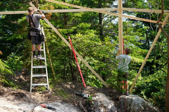
The challenge began with the batter boards. With no topsoil for driving typical wood stakes, the crew had to drill into the stone and drive predrilled steel grade stakes, then fasten the grade stakes to 2×4 posts for the batter boards. On the downhill side, where the posts would have to be well above head height, the crew came up with the ingenious workaround of screwing the batter boards to conveniently located trees. They set the elevations of the batter boards using a Bosch rotary laser, but they squared off their string lines using the old-school method of establishing a 3-4-5 triangle.
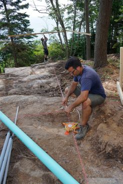
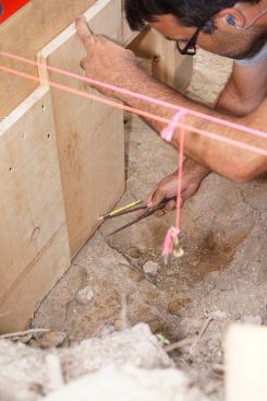
Despite the makeshift layout method, the string lines were remarkably accurate: Cross-taping the rectangular string setup showed that the square was precise within 1/16 inch. To locate the piers, the crew measured out along the strung lines and marked locations with a Sharpie marker, then tied more strings at the marked locations with weights on the ends to form plumb lines, checking their layout with a 6-foot level where possible. They marked locations for their piers directly onto the stone using Sharpie markers.
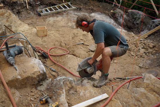
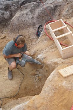
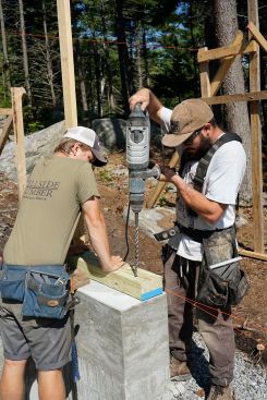
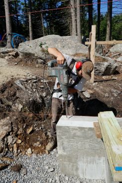
As luck would have it, some of the piers fell out at locations with a sharp irregularity in the rocky contour. The ocean side of the building was an outdoor deck, and the piers for the deck could be moved a few feet from side to side in order to find more suitable ground for the footing. But for the main building, layout was constrained by the requirements of the structural system. So where the stone contours were too rough, the crew had to remove stone to create a more nearly level footing base and to reach sound rock. This they accomplished using a Husqvarna masonry wet-saw and a Bosch rotary hammer (a tedious and time-consuming process).
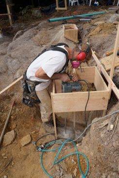
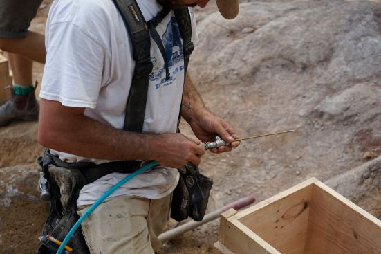
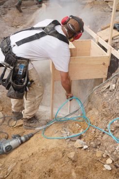
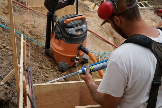
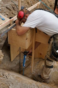
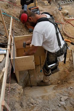
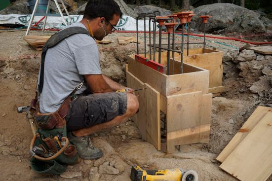
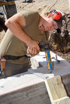
Next, the crew set about building forms, using 1×12 pine boards. They screwed together boxes of pine in the required dimensions, then used short rips of pine to make legs for the upper box. With the form’s top outline defined, but while they still had room to access the ground, they drilled into the rock with a rotary hammer, blew out the holes with compressed air, injected epoxy into the holes, and drove 1/2-inch rebar into the stone at the locations and spacing specified by the engineer. This would anchor the piers against sliding and uplift in response to wind forces.
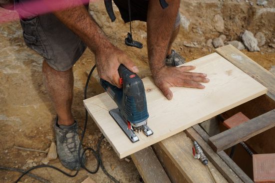
The crew scribed pieces of 1×12 to match the irregular rock surface, cut the pieces with a jigsaw, fine-tuned the curves using an angle grinder, and placed the form boards in contact with the stone. Preparing the grade, driving the rebar pins into the rock, and piecing together all the stem-wall forms took several days of labor.
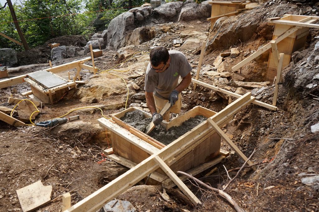
Now it was time to place concrete. The crew had about a hundred bags of concrete on hand and two electric mortar mixers. With both mortar mixers going, they mixed small, two-bag batches using a measured amount of water, dumped the concrete into five-gallon pails, carried the pails over the rough surface to the forms, and dumped the concrete into the forms.
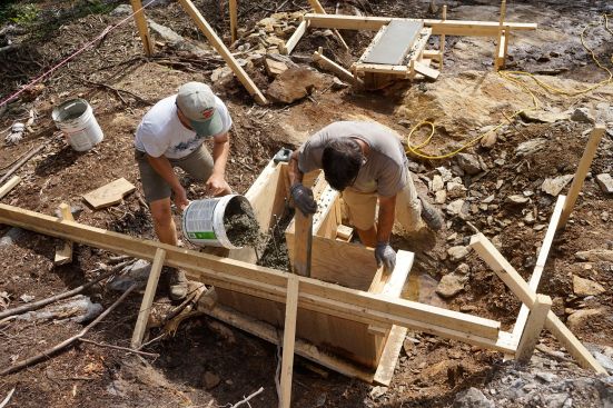
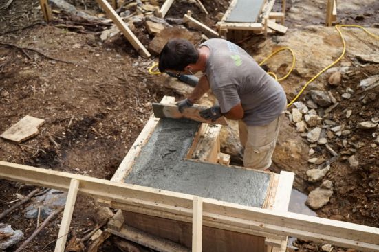
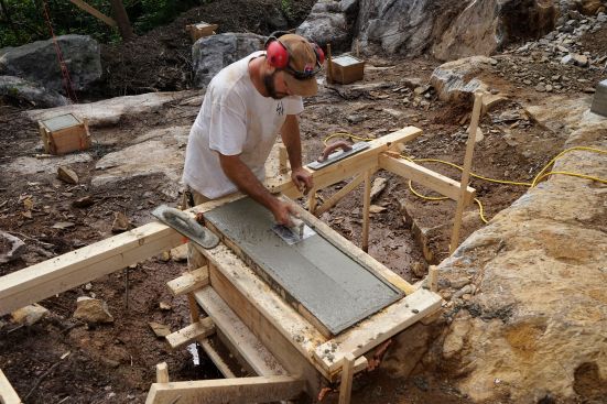
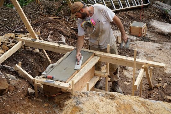
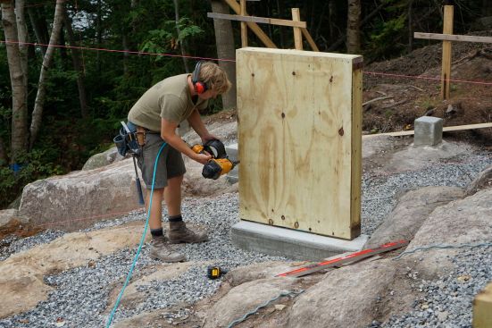
The crew places concrete and frames up stemwalls.
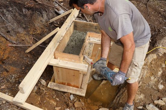
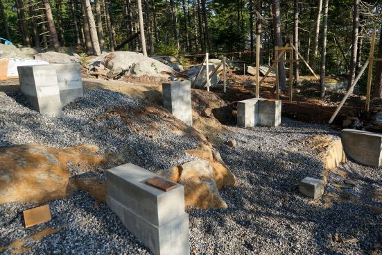
The crew consolidated the concrete by rodding and tamping it with a short board, and by vibrating the outside of the forms using a reciprocating saw with a site-fabricated wooden extension. They struck off the concrete level with the form tops using a straight piece of board. When the concrete was set but still workable, they finished the top surface using an edger and a finishing trowel. Two days later, they stripped the forms.
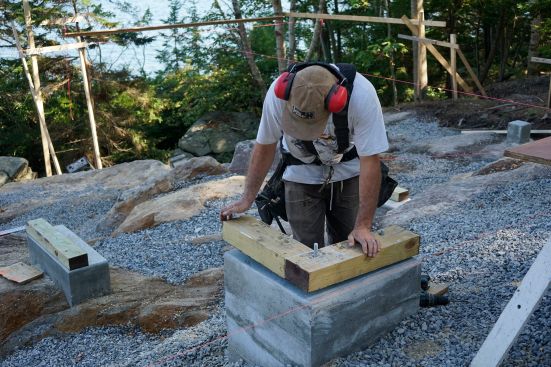
Now the crew had to prepare for floor framing. Some of the piers were at full height and would need only a simple sill. But others were short of the floor and would need stem walls of various heights to bring the structure up to the first-floor frame level. In any case, the crew had to start by installing 4×6 treated wood sills on all the piers.
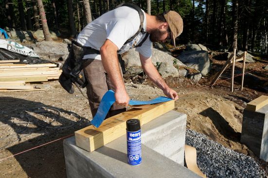
After cutting the 4×6 lumber to length, the crew set about applying Henry Blueskin WB25 waterproofing membrane to what would be the underside of the sills, in order to create a capillary break. The membrane would not adhere to the treated wood unless the wood was first primed with Henry Spray Prep.
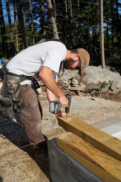
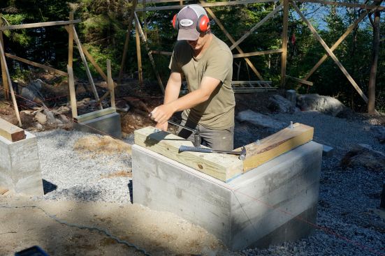
Once the membrane was applied, the crew drilled holes for anchor bolts in the sill material. This required careful layout in some cases. In places, the locations of a double-LVL floor beam and doubled dimensional joists had to be worked around. Also, some of the hold-downs for the one-story building’s shear walls needed to be anchored into the same piers as the anchor bolts, in specific locations.
After the sill plates were drilled, the crew set the sills in place on the piers and used the holes in the sills as guides for drilling into the concrete. They drilled 7 inches deep into the concrete, blew out the holes with compressed air, and epoxied threaded rod into place for the sill anchors. Once the epoxy had set (which took only a few minutes), the crew set the sills down over the threaded rod and applied nuts to secure the sills in place.
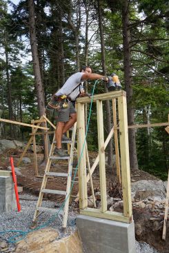
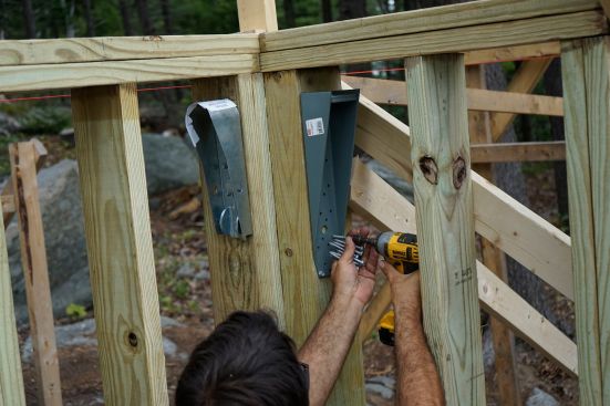
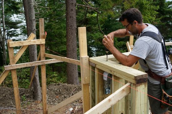
Now it was time to build stem walls. Crew leader Mark Pollard determined the stud length for each wall by setting up the rotary laser again and measuring from the sill up to the laser beam. He cut stud and plate packages for each wall and brought the lumber to each of the piers. Then the crew framed the stem walls.
At the top of several of the stem walls, hold-downs were required by the structural plan. The carpenters installed these hold-downs as they went, and drilled down through the top plates of the walls to accommodate the threaded rod that would complete the hold-down assembly. Then the crew applied 1/2-inch plywood to the inside face of each wall as specified in the structural plan, nailing the plywood at 2 inches on-center at the perimeter and 6 inches on-center in the field.