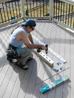
Aluminum balusters are affordable, visually appealing, and low maintenance. The ones I use most commonly are made by Deckorators; these hollow tubes slip over connectors that are screwed to the 2x4s that form the top and bottom rails (Figure 1).
My carpentry crews saw the advantages of these balusters, but laying out the bottom and top 2×4 rails, and then accurately screwing down each baluster connector was slow and awkward. Consequently, we came up with a jig to speed up the process.
Horizontal-Rail Jig
Start with some 1-inch screws, a 6-foot length of 1×4 cellular PVC (such as Azek), two 6-foot strips of 5/8-inch-by-3/4-inch PVC, and PVC glue (Figure 2). I use PVC instead of wood; wood swells and shrinks as it gets wet or dries out, while PVC is more stable.
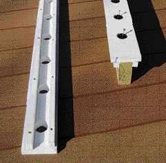
Figure 2. The jig is made from PVC sheet such as AZEK, preferred over wood for its stability. Holes drilled on 4 1/2-inch centers hold the baluster connectors as they're screwed home.
I draw a line down the center of the 1×4 and mark it every 4 1/2 inches, which reflects my standard baluster layout. The 1×4 needs to be drilled at these marks to accept the baluster connectors. For Deckorators’ 34 mm baluster connectors, I drill 35 mm diameter holes at each layout mark. A drill press is ideal for this task, but you can get by with using a hand-held drill if you’re careful.
Then I attach the narrow PVC strips to the 1×4. When the jig is in use, these strips will locate and secure the 1×4 over the railing’s 2x4s. I center the drilled 1×4 over the narrow edge of a straight 2×4 and screw baluster connectors to the 2×4 through the two end holes and the center hole in the 1×4.
Keeping the 1×4 on these connectors, I flip the assembly upside down. Next, I drill pilot holes through the PVC strips on the 3/4-inch side on about 12-inch centers. With PVC glue brushed onto the exposed 1×4, I screw the PVC strips to the 1×4 against the 2×4, making a U-channel out of the PVC. The strips should be snug to the 2×4, but loose enough that the jig can slide on and off without a struggle.
Using the jig is simplicity itself. Lay it on top of the 2×4 rail so that the distance from the last layout holes to each end of the 2×4 is equal and less than 4 inches from the end — to comply with code. It’s a good idea to mark a centerline across the first three holes on each end of the jig and transfer them down the sides of the jig. When adjusting the placement of the jig, you can measure to the ends of 2×4 from these lines instead of trying to measure to the center of the hole.
Install one baluster connector by dropping it in one of the predrilled holes and screwing it home (Figure 3). The jig is now held in place and the rest of the connectors can be installed through the layout holes. This method allows for consistent baluster spacing and saves a surprising amount of installation time.
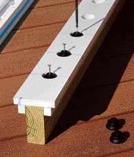
Figure 3. Lines drawn square down the side of the jig ease its alignment with the ends of the 2×4 railing. Without the lines, placing the jig to provide even spacing of the end baluster connectors would require measuring to the center of the jig's holes. To use the jig, simply place it where you want on the rail, drop in a connector, and screw.
Making the Stair Rail Jig
A jig can be made for the stair rail using a similar method. Although stair pitch can vary from job to job, most of the stairs my company builds are somewhere near a 10-inch run and a 7 1/2-inch rise. I’ve found that one jig made for a 35-degree angle works on most of them, particularly because Deckorators makes an adjustable baluster connector for stair rails.
There are two main differences between this jig and the one for level rails: The holes are drilled at a 35-degree angle, and they’re spaced at 51/2 inches. Because this spacing is measured on the stair’s rake angle, it results in a baluster spacing of just less than 4 inches.
A drill press is definitely preferred to make this jig, but if careful, you can get by with an angle guide and handheld drill. The stair jig works better if you can pre-mount a baluster connector on the rail section, which helps keep the jig from slipping downward. You could also drill a hole in the PVC to tap-screw it temporarily in place. Clamps work as well.
Threaded Rods for Stability
Another method I’ve adopted when using aluminum balusters doesn’t save time, but I feel it improves the rail’s stability. I install a 1/4-inch galvanized threaded rod to draw together the top and bottom sections of rail to prevent sagging or bowing, which might cause the balusters to become loose or fall out (Figure 4). This approach works as an adjunct to the installation of short vertical legs between the deck and bottom of the rails to keep the rail from sagging.
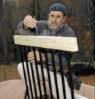
Figure 4. To firm up the assembly, the author drills a through hole at one of the central baluster connectors and runs a length of threaded rod between the upper and lower rails.
Begin by dropping a baluster connector into a middle hole in the baluster jig, and drilling a 5/16-inch hole through it. Continue the hole completely through the 2×4 or rail-material sections. Do this to both the bottom and top rail sections.
Follow up by drilling a 7/8-inch-diameter hole about 1/2 inch deep through the top of the upper 2×4 and the bottom of the lower 2×4.
After the holes are drilled, feed the rod through the 2×4, the drilled-out connector, the baluster, and the other connector and rail section. Installing and tightening nuts and washers clamps together the rail.
I like to double up on the nuts to prevent them from loosening over time. The long ends of the threaded rod are sawn off flush with the rail after nuts are tightened. A reciprocating saw with a metal-cutting blade makes quick work of this.
The rail cap covers the top hole, but the hole in the bottom rail remains exposed. If you set the nuts even with the end of the rod on this end prior to installation, you can recess them into the 2×4 far enough to allow a plug.
Baluster ManufacturersDeck Solutions 800/233-9349 BW Creative Wood Industries 800/667-8247 Deckorators 800/332-5724 Mile High Balusters 303/991-2285 Fortress Iron Railing & Fence Systems 866/323-4766 |