The easiest way to create the curved components of the niche is …
The easiest way to create the curved components of the niche is by laminating strips. The author starts with the rails for the curved top, resawing and planing them to just over 1/8-inch thick. Five strips provide the desired finish thickness.
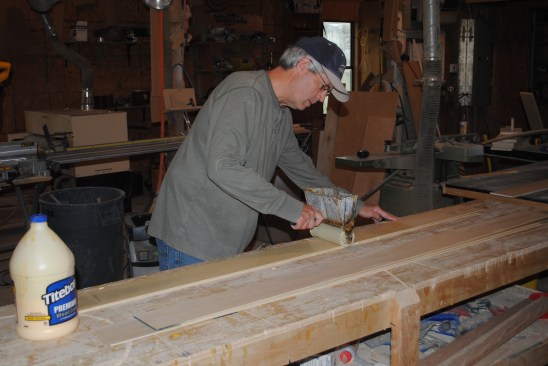
The author applies an even layer of carpenter's glue to the stri…
The author applies an even layer of carpenter's glue to the strips.
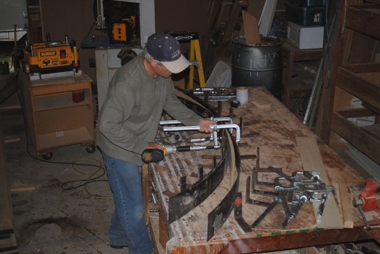
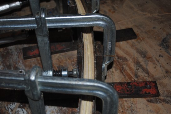
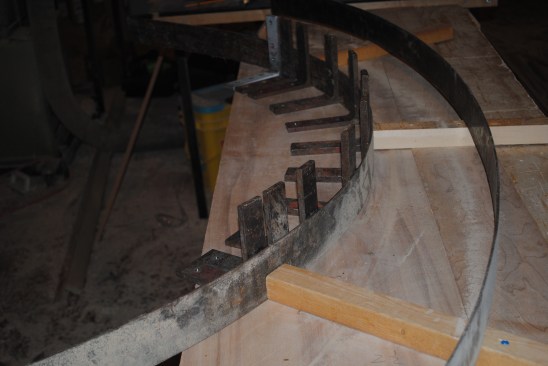
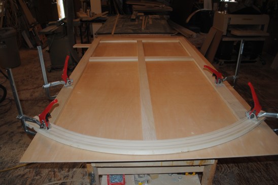
Angle irons screw to the radius for the curve that the author ha…
Angle irons screw to the radius for the curve that the author had drawn on the bench top. Thin pieces of steel sandwich the strips into the shape of the curve.
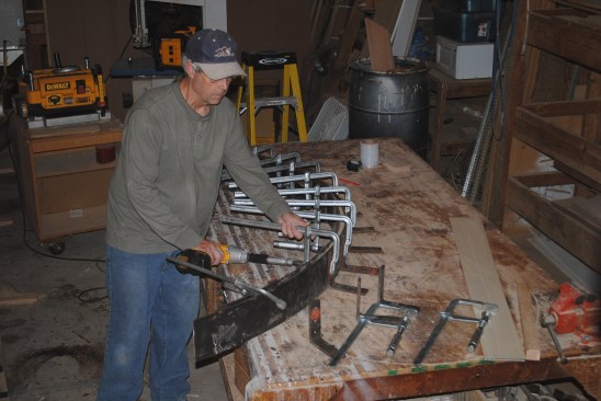
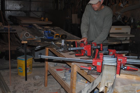
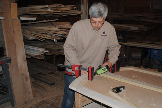
Heavy duty angle irons distribute the clamping pressure evenly o…
Heavy duty angle irons distribute the clamping pressure evenly over the width of the lamination. Sliding bar clamps equipped with a nut on the tightening screw make it easy to apply even pressure over the lamination using the clutch on a drill driver.
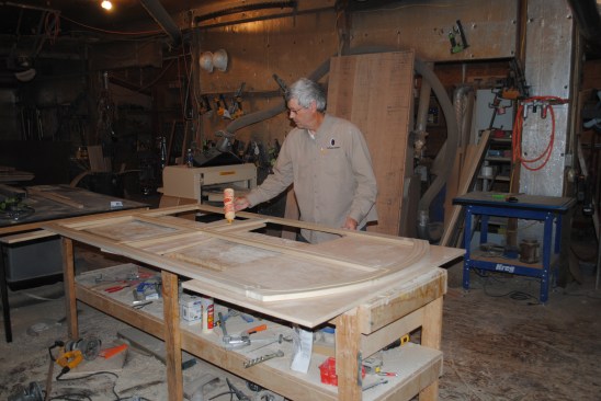
When the right amount of clamping pressure has been applied, glu…
When the right amount of clamping pressure has been applied, glue should ooze from the seams between the strips.
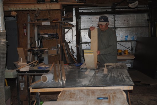
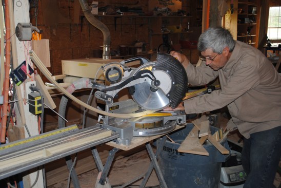
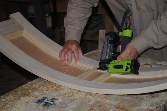
Author carefully runs the curved lamination through a table saw …
Author carefully runs the curved lamination through a table saw to clean up the edges.
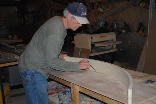
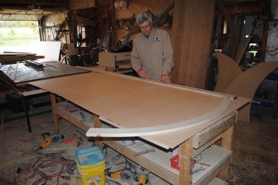
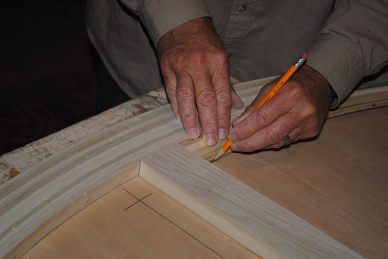
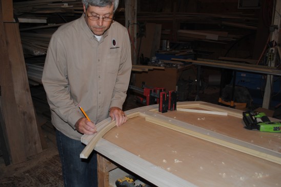
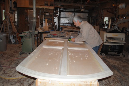
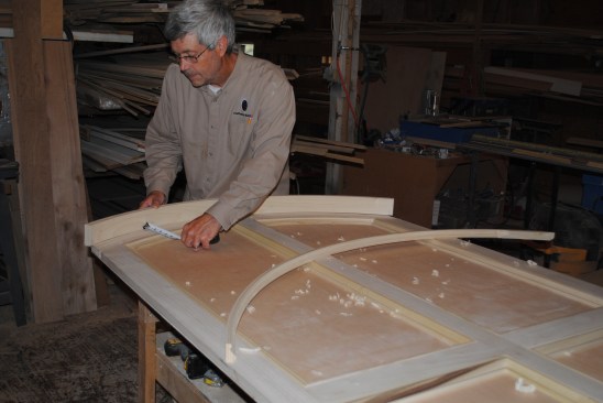
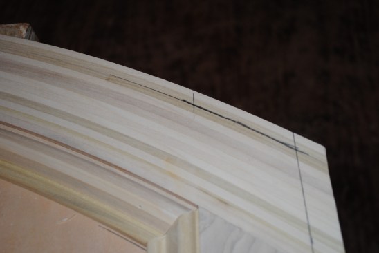
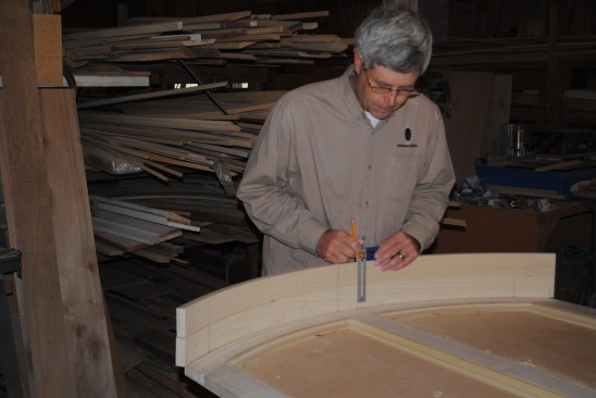
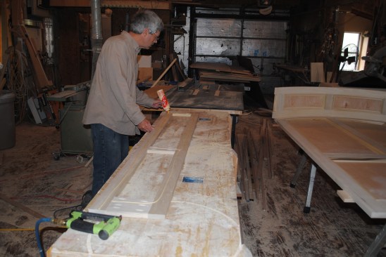
The author uses the lamination for the top rails to scribe an ar…
The author uses the lamination for the top rails to scribe an arc 3 1/2 inches (the width of the back-panel rail) from the inside for the radius of the rail and the panel molding.
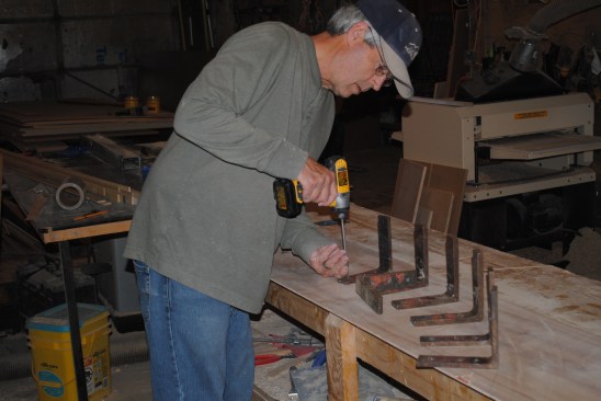
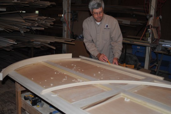
Angle irons screw to the bench top along the arc drawn on the be…
Angle irons screw to the bench top along the arc drawn on the bench top.
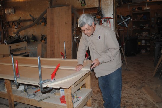
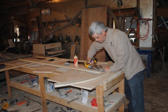
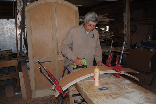
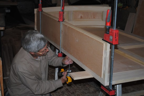
Because the top rail and molding for the back panel have to be g…
Because the top rail and molding for the back panel have to be glued on the flat, the author screws 2×2 blocks to the bench top to raise the level of the glue up. The raised surface centers the clamping pressure on the pieces being laminated and it minimizes the surface area that gets glued by the squeeze out.
As before, the lamination begins with milling strips just over 1…
As before, the lamination begins with milling strips just over 1/8-inch thick.
This glue up creates the both the top rail and the curved panel …
This glue up creates the both the top rail and the curved panel molding for the back panel so the authorglues up both pieces at once. After applying glue to each set of strips (with a dry layer between the two sets) and he places them together in the jig for the glue-up.
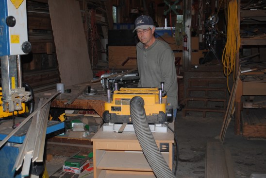
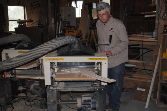
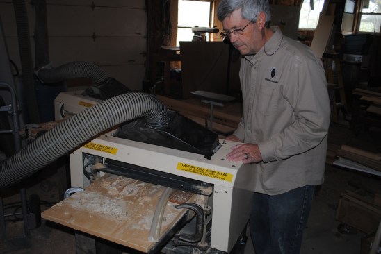
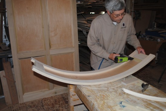
This time the author planes the blanks for the curved rail and t…
This time the author planes the blanks for the curved rail and the panel molding with a Woodmaster Planer/Molder to clean them up.
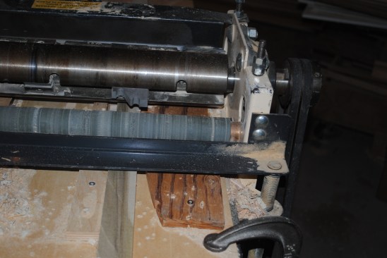
Cutter knives attach to the planer head to create the profile of…
Cutter knives attach to the planer head to create the profile of the curved molding.
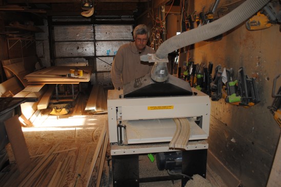
The cover is removed from the machine to show the setup for the …
The cover is removed from the machine to show the setup for the panel moldings for the back panel. The guides screwed to the temporary table allow the author to mill both curved and straight moldings with the same set-up.
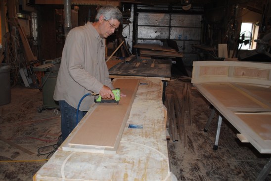
Here the author feeds the stock through the planer for the moldi…
Here the author feeds the stock through the planer for the molding for the back panel that had to be profiled on the flat.
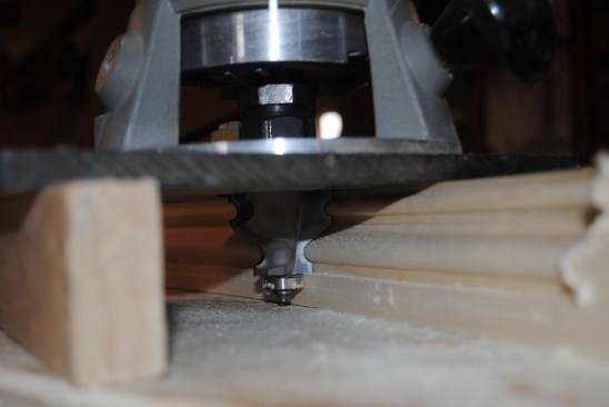
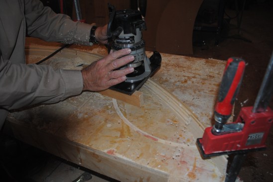
The panel molding for the curved top had to be profiled on edge,…
The panel molding for the curved top had to be profiled on edge, so the author used a bearing-guided bit in a router to do the cutting.
A block attached to the table of the router keeps the router fla…
A block attached to the table of the router keeps the router flat and perpendicular to the molding stock.
1
of 13
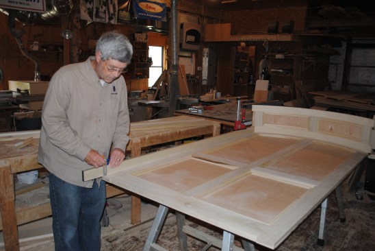
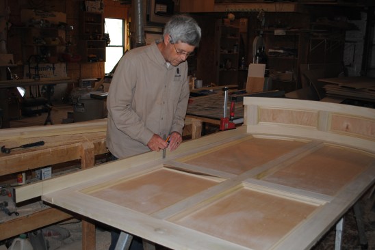
The first step in building the back panel is drawing lines for t…
The first step in building the back panel is drawing lines for the stiles on the 1/4-inch plywood back material.
The author then scribes the tops of the stiles to the curve of t…
The author then scribes the tops of the stiles to the curve of the top rail.
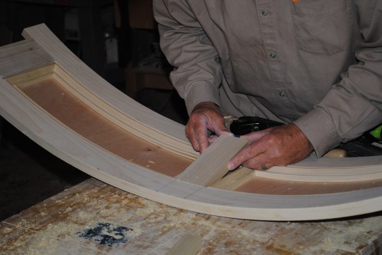
The author clamps each piece in place as it is cut to fit. Here …
The author clamps each piece in place as it is cut to fit. Here he uses a hand plane to shape the top end of the center stile where it joins the curved rail.
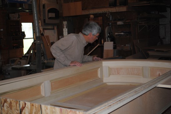
Here the stiles and rails for the back panel have been cut and f…
Here the stiles and rails for the back panel have been cut and fit into place.
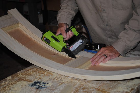
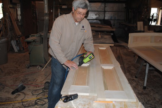
Working from the back side, pocket screws and glue connect the f…
Working from the back side, pocket screws and glue connect the frame pieces for the back panel.
The author applies a bead of glue to the back of the frame befor…
The author applies a bead of glue to the back of the frame before setting the plywood in place.
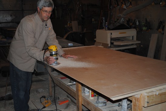
After gluing and nailing the plywood back into place, the author…
After gluing and nailing the plywood back into place, the author uses a small router with bearing-guided bit to remove the excess material from around the frame.
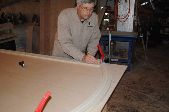
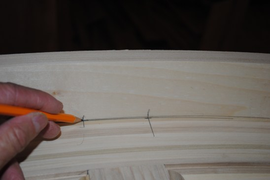
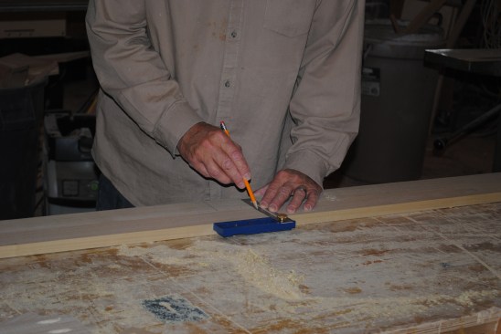
To lay out the panel molding for the back panel, the author uses…
To lay out the panel molding for the back panel, the author uses a short piece of molding to draw lines that will help to precisely determine the angles of the adjoining pieces.
With the layout lines, the author then marks the inside and outs…
With the layout lines, the author then marks the inside and outside of the intersecting joint.
With the cut line drawn, the author simply aligns it with the la…
With the cut line drawn, the author simply aligns it with the laser line of the saw to make the cut.
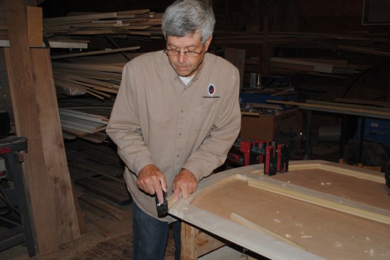
Author uses a plane to fine tune the fit of the panel molding pi…
Author uses a plane to fine tune the fit of the panel molding pieces.
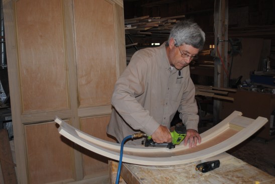
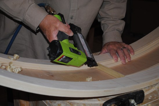
A clamp draws the curved molding into position where it can be g…
A clamp draws the curved molding into position where it can be glued and nailed into place.
The author attaches panel molding on the bottom sections to comp…
The author attaches panel molding on the bottom sections to complete the back panel assembly.
1
of 15
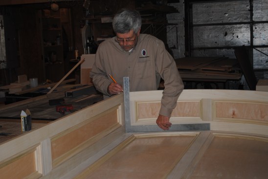
Before building the curved top, the author measures up and lays …
Before building the curved top, the author measures up and lays out precisely where the top will fit against the back panel.
Next the author lays out the positions of the side panels.
A close-up of the corner shows the corner where the layout lines…
A close-up of the corner shows the corner where the layout lines intersect.
With the top positioned, the author marks registration lines on …
With the top positioned, the author marks registration lines on the curved rail to align it with the stiles of the pack panel.
The registration lines also mark the location of the stiles for …
The registration lines also mark the location of the stiles for curved top. Here the author transfers the lines between the rails.
Pocket screws and glue join the stiles to the curved rails. The …
Pocket screws and glue join the stiles to the curved rails. The center stile is left off intentionally at this point.
The 14-inc plywood back is flexible enough to bend over the curv…
The 14-inc plywood back is flexible enough to bend over the curved top. After applying glue to the frame, the author staples on the back, using clamps to hold the plywood to the frame.
After flipping the curved top panel over, the author begins atta…
After flipping the curved top panel over, the author begins attaching the panel molding. Note that the center stile is still missing.
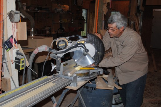
Cutting the curved panel molding requires the position of the cu…
Cutting the curved panel molding requires the position of the cut to be perfectlyflat on the saw table while the ends curve up.
The curved molding sections glue and nail into place.
The author nails in the final piece to complete the molding for …
The author nails in the final piece to complete the molding for the first side of the curved top.
Then he completes the molding for the other side.
Finally the author cuts the center stile and slips it into place…
Finally the author cuts the center stile and slips it into place. Because the sides of the stile are straight, it's much easier to adjust the fit of this piece, rather than fussing with the fit of the panel molding.
When the fit of the center stile is satisfactory, the author glu…
When the fit of the center stile is satisfactory, the author glues and nails it into place.
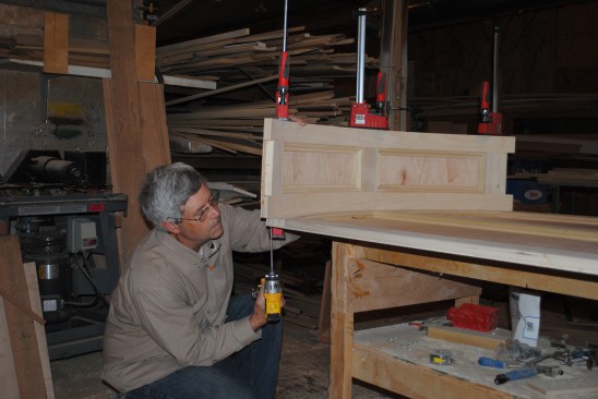
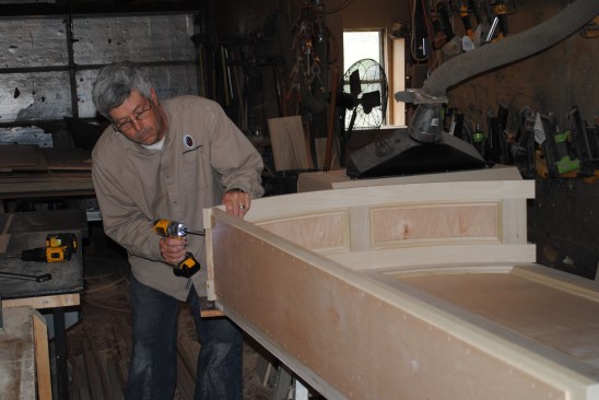
When the curved top is finished, the author clamps it in place o…
When the curved top is finished, the author clamps it in place on the back panel and joins them together with screws.
1
of 13
The author sets the stiles for one of the side panels on the lay…
The author sets the stiles for one of the side panels on the layout lines drawn earlier and marks the angle where the piece intersects with the top.
The author first marks the length of the side stiles.
As with the top, the author marks the rail locations on one of t…
As with the top, the author marks the rail locations on one of the stiles.
He then transfers the rail positions to the second stile.
As before the sides are assembled with pocket screws. Here the a…
As before the sides are assembled with pocket screws. Here the author applies a bead of glue for the plywood back.
The plywood back staples to the frame.
Panel molding completes the side panels.
After aligning the side panels with the layout lines made earlie…
After aligning the side panels with the layout lines made earlier and clamping them in place, the author screws them to the back panel.
The author uses a framing square to align the side panel square …
The author uses a framing square to align the side panel square to the back panel and marks the position on the curved top.
Holding the side on the square mark he just made, the author scr…
Holding the side on the square mark he just made, the author screws the top to the side panel.
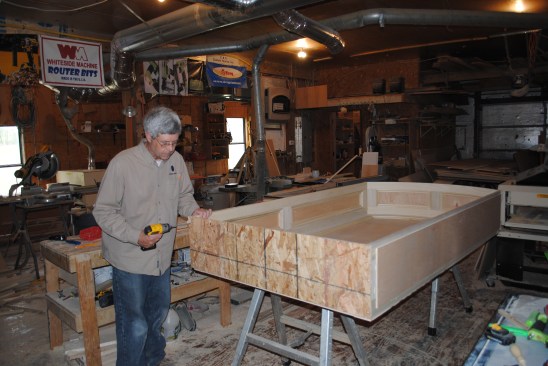
To keep the bottom of the niche stable for cutting the trim and …
To keep the bottom of the niche stable for cutting the trim and for transportation, the author screws a piece of OSB to the bottom edges of the sides and back.
Temporary winglets attach at right angles to the sides to suppor…
Temporary winglets attach at right angles to the sides to support the casing while the pieces are cut and fit. The author can then fit the curved top casing (made from MDF for this paint-grade project) to the sides on a stable, flat surface.
The author will join the casing together with dominoes after he …
The author will join the casing together with dominoes after he installs the niche, so he cuts those slots while still in the shop. The casing pieces are then taken to the jobsite unassembled along with the completed niche.
1
of 6
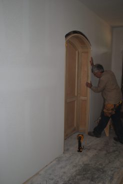
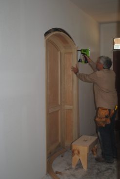
After removing the temporary OSB spreader from the bottom, the a…
After removing the temporary OSB spreader from the bottom, the author slides the completed niche into the prepared hole in the wall.
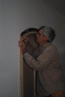
Installing the niche is much like putting in a pre-hung door. Th…
Installing the niche is much like putting in a pre-hung door. The author begins by attaching a top corner.
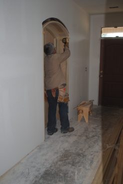
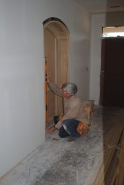
He then plumbs the assembly and shims
it in place much like a p…
He then plumbs the assembly and shims
it in place much like a prehung door frame.
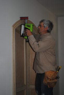
After attaching the niche to the framing on both sides of the op…
After attaching the niche to the framing on both sides of the opening, the author nails on the jamb casing.
Before attaching the head casing, the author slips dominoes into…
Before attaching the head casing, the author slips dominoes into the slots along with glue.
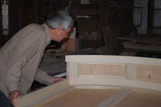
Rarely do I build a stock plan for a home without the client making a few changes. Recently, clients asked us to grow the front section of their house by 4 feet to enlarge the master closet and the dining room. This bumped out the gable roof, but aside from requiring additional material, the framing didn’t change much. The entry hallway, though, was now long and narrow, a little like a bowling alley. I decided to break up the long hallway wall with a recessed paneled niche that bumped into the dining room, which the added space had made wider.
For a unique look, I designed the niche to have a radius top. The framers built a 46-inch-wide-by-16-inch-deep recess in the hallway wall, and with the 9-foot ceilings, there was plenty of room for a header below the top plate. To let the header conform to the curve of the niche, I asked the framers to add a couple of 16-inch OSB rippings below the structural header to create a hollow “sub-header” that I could cut out later to the curve of the niche. The best part—I would be able to build the niche in my shop and then install it in one piece.
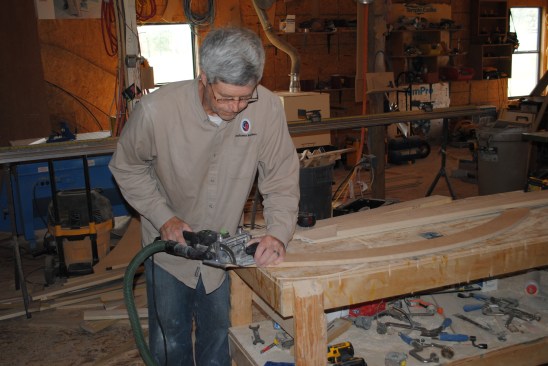
Paint-grade Solutions
The woodwork in the house was to be painted, so I was able to cut some of the curved parts, such as the casing, out of MDF panel stock. The other curved parts—the curved jamb rails and top rail and molding for the back panel—had to be strip-laminated out of wood. (Note that if the niche had been a stain-grade piece, I would have needed to glue the strips back together in the same order that they were cut from the board).
I cut the profiles for the panel molding for the back wall and for the casing on a Woodmaster Planer/Molder—a machine that can be set up with a knife that cuts molding profiles, instead of the standard straight planing knives. I probably could have purchased radiused flex molding for these trim parts, but making them from scratch gave me more design flexibility.
The Right Radius
To get the proper proportions for this type of arch, I like to use the width of the opening for the radius. The rough opening was 46 inches; allowing room for 1-inch-thick sides along with space to shim, I decided to make the inside of the niche 42 inches wide—so that became the radius for the curved top.
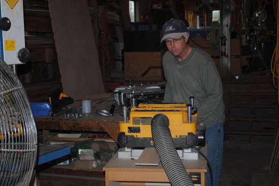
When you’re strip-laminating, the more layers you use, the stronger and more stable the curved piece will be. In my experience, five layers work well for making a curved jamb or a panel molding. For the parts for the curved top section that I strip-laminated, I aimed for the total thickness of the five layers to be about 13/16 inch. After the glue-up, I planed the pieces down to true the edges.
I am not comfortable enough with my bandsaw to cut the strips for the laminations; instead, I resaw the boards on edge slowly and carefully on my table saw. During this resawing, the boards occasionally pinch and bind and I rarely get a perfect cut. So I surface all the strips with a bench-top planer to just under 3/16 inch per layer to make five layers that stack up to 13/16 inch.
I screw heavy-duty angle irons to the bench top to make the radiused jig, and laminate the pieces together with carpenter’s glue. Even with five layers, there is always a little spring back when I remove the clamps, so I make the parts for the curved top jamb first, and then use that jamb to lay out the curve for the back wall.
Gary Striegler, a JLC contributing editor, owns Striegler and Associates in Fayetteville, Ark., and teaches workshops at the Marc Adams School of Woodworking.