My company does a lot of work in the scenic eastern hills of Orange County in California, so we often build what we call “view decks.” Not only are these decks usually located on a steep grade, they are often detached from the home to extend the footprint of the backyard living area. A project that we recently completed is a good example of this type of deck.
While this particular view deck may not look like anything that would be too complicated to build, it is located—like most of our projects—in a Class D high-risk seismic zone. Because the deck is freestanding, determining its seismic load (using the standard ASCE 7-10 Minimum Design Loads for Building and Other Structures, ascelibrary.org) did not need to take into account the seismic load path through the house. Even so, our local AHJ and engineers did have specific seismic requirements that needed to be met to guarantee a safe, bullet-proof deck in the event there should be an earthquake.
Footings
Though we don’t have to worry about frost in this part of California, there are certain rules for footings that we do have to follow. On slopes, for example, footings must be a minimum of 30 inches deep, and we have a “5-foot-to-daylight” rule for the footings. This means that there must be 5 feet of undisturbed soil between the bottom of the footing and daylight when measured along a line leveled across the bottom of the footing.
To properly locate the footings on a sloped site like this, we like to stake up 2x4s to create a mock footprint of the deck. This simplifies the layout process, and the 2x4s also double as batter boards from which we plumb down to establish finish deck and footing placement.
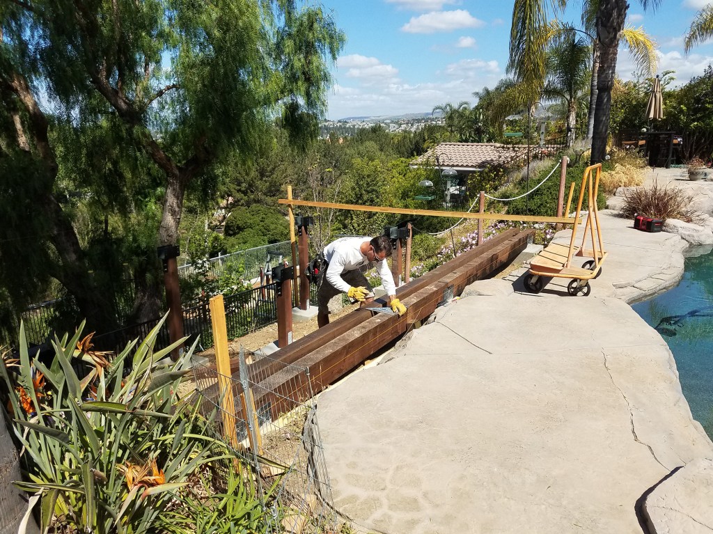
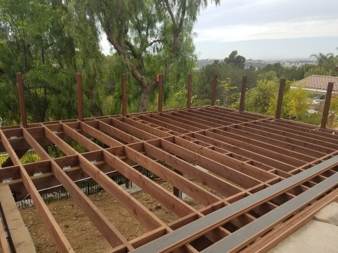
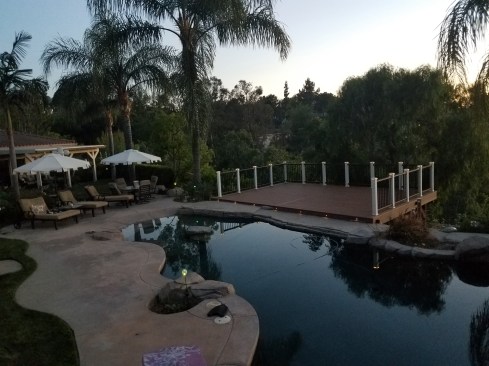
The freestanding deck is located on a steep slope and just one step up from a hardscaped pool surround. Batterboards are essential for an accurate layout.
Nine 2-foot-square-by-30-inch-deep footing forms were filled with 4,500-psi concrete.
Metal hardware to connect the framing to the footings was embedded in the concrete during the pour.
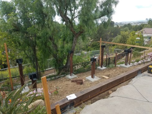
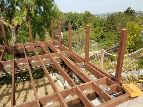
The upper three footings support a continuous 6×12 PT beam; the other footings support 6×6 posts.
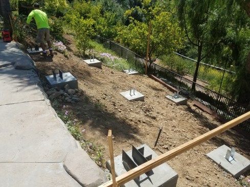
Our footing plan called for nine 2-foot-square footings, each reinforced with five lengths of #5 rebar in a mat located 3 inches off the bottom of the footing. That required about 4.5 yards of 4,500-psi concrete, delivered to the footings by a pumper truck parked up in the home’s driveway.
Hardware embedded in the footings ensures a strong load path between the deck framing and the ground. On top of three footings, we used Simpson Strong-Tie CCQM and CCTQM column caps, as a beam would sit on those footings. On the other footings, which would support posts, we used SST CBSQ column bases.
Framing
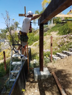
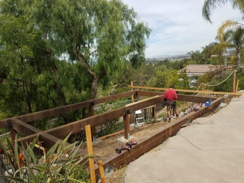
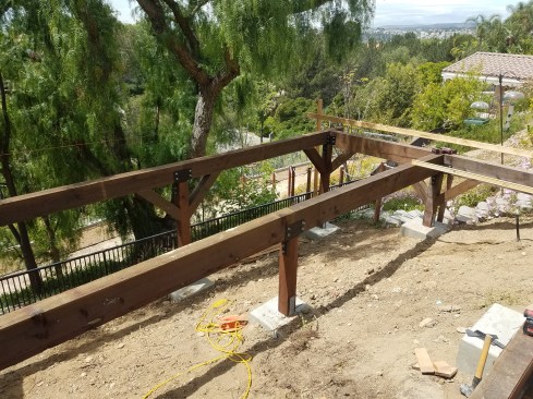
The engineer’s framing plan features a perimeter beam detail with sawn (rather than built-up) 6×10 and 6×12 treated Doug fir beams running both parallel and perpendicular to the joists. By connecting the drop beam at the front of the frame and the drop beam in the back, all the deck framing works together as a system. This also allows for solid connections for knee braces in all directions; these eliminate vibrations in the deck frame and—more importantly—limit lateral movement if an earthquake ever comes into play.
Michael Walter
The carrying beams were tied together with perpendicular perimeter beams to reinforce the frame against seismic loads.
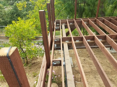
The frame was also reinforced in both directions with knee braces that were fastened to the beams and columns with 1⁄2-inch-diameter HDG all-thread rod.
Here in California, large sawn beams are readily available, so naturally, SST column caps and other hardware that’s sized to fit the beams are as well. On this project, we used SST ECC66 HDG galvanized brackets, but when we’re building near salt water, we use stainless steel hardware. Before installing the brackets, we washed them with acetone, then spray-painted them with rattle-cans of Rust-Oleum primer and black paint to give them a custom look and to match the rest of the deck hardware.
The framing lumber is ACQ-treated incised browntone Doug fir, which blends a little better into the landscape than non-stained PT lumber. It’s all rated for ground contact, but for extra durability, we specced heavier-duty 0.60 (AWPA UC4B) retention level for the 6-by material.
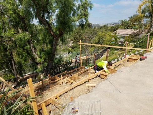
Even though most of the deck is elevated, 2×8 joists were needed to avoid having a tall step up onto the deck from the adjacent patio.
Because the top of the deck is right on grade where it meets the patio, I needed all the room I could get without cutting the grade, which would have required a different permit. So we installed 2×8 joists 16 inches on-center. Common practice here when installing joists is to block over each beam and install Simpson A-35 connectors on each block to help limit lateral movement and to provide some uplift value.
Joist blocks were pre-fitted with SST A35 framing angles.
Then they were fastened to the beams to help limit lateral movement and to provide some uplift value.
Around the rim, we decided to double the joists. This turned out to be a nice detail that eliminated ladder blocking for our picture-frame decking and made for a stiffer post installation.
Guards
When building decks, we follow California’s statewide residential building code, which requires 42-inch-high guardrails on all decks that are more than 30 inches above the ground. To ensure that our posts met code load requirements (according to Table R301.5 in the 2016 CRC, guards must be able to support a 200-pound concentrated load applied in any direction at any point along the top), we made all of our guard post connections using SST DTT2Z brackets as needed, along with plenty of blocking.
The deck posts were 45 inches high and through-bolted to the double rim joist with SST DTT2Z anchors, reinforced with plenty of blocking.
The posts were located on 4-foot centers because of the shallow 2×8 joists.
Because we used 2×8 joists, the engineer specced 4-foot centers for the posts. To plumb the posts and make sure they were in alignment, we took our time and used plenty of weather-resistant tapered composite shims during installation.
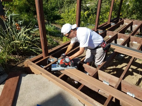
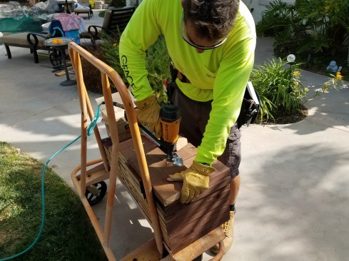
The author—a self-confessed “toolaholic”—used a Mafell cordless crosscut saw purchased in Germany to cut the miters for the picture-frame deck border.
Decking
Picture-frame borders are standard for all our decks. Another signature decking detail for our company is a seam board installed up the middle of the deck, to eliminate butt joints. On this project, we used Trex Transcend Tiki Torch decking, which is a Southern California favorite.
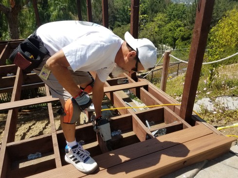
The Trex Transcend decking was fastened to the joists with Tiger Claw clips, installed using an air nailer equipped with scrails.
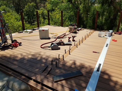
Installing a seam board in the middle of the 28-foot-wide deck avoided the need for butt joints in the decking.
We installed the decking using Fasten-Master Tiger Claw TC-G clips and pneumatically-driven scrails. Not only are these stainless steel clips quick to install, it’s easy to replace deck boards without removing them or stressing the scrails. To replace a board, we just work backward, and the board pulls up easily; to reinstall the decking, we then just turn the clips 180 degrees and place the new board.
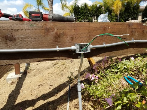
Power to the deck runs through buried watertight PVC conduit.
It also supplies low-voltage LED lighting.
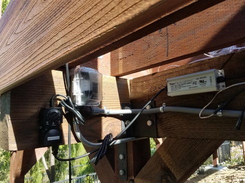
Lighting
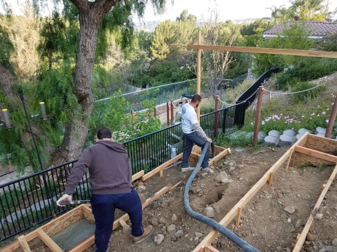
Before we installed the decking, we wired the deck for low-voltage LED lighting. As a licensed general contractor here in California, I can do the electrical work on a project as long as I do two other trades as well (on this deck, I also did the framing and concrete work). The power supply to the deck runs through PVC conduit buried 18 inches deep in the ground. Above ground where it is exposed, the wiring runs through flexible and rigid metal conduit.
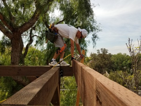
The author used a laser distance measurer to determine guardrail lengths.
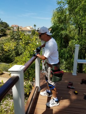
The Trex railing is 42 inches high, to meet California code requirements.
The view deck is a beautiful extension of the home’s small outdoor living area.
Each of the 45-inch-tall guard posts is topped with a lighted post cap, and there are seven riser lights at the transition between the deck and the hardscape surface around the pool.
Photos courtesy MLW Construction