Floor Framing
By the time we were ready to bolt down the PT sill and get started on the framing, we had completed most of the structural repairs to the existing house. Floor framing was straightforward — except for having to cut 11.25-degree bevels on both ends of 15 pieces of sill and rim joist, and bevel seven of the 11 2×12 floor joists.
We used 2×12 joists to ensure that we ended up with a stiff floor, notching the bottoms at each end to match the 2×10 rim joists. (Code allows notching at the ends of joists — up to a fourth the width of the member, or 2 13/16-inch in a 2×12). We also installed bridging down the centerline, then sheathed the floor with 3/4-inch T&G plywood.
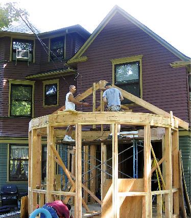
Wall Framing
To lay out the walls, we had to take into account the widths and angles of the polygon sections, the required rough openings for the windows, and the frieze board running around the perimeter of the existing house. We began by cutting pairs of 2-foot 11 13/16-inch-long plates for each wall section and laying them out around the perimeter of the deck. To tie the wall sections together, we cut the double top plates so they overlapped the bisected angles where the plates met. To further strengthen the wall, we ripped angled 2-by fillers to fit into the triangular-shaped voids between the outside edges of adjoining studs.
There was enough room in each wall section to accommodate a window rough opening, but not enough for a pair of trimmers to support a header. Instead, we carried the roof loads with a continuous box header installed above the double top plate — a pair of 2x8s nailed together with lumber spacers, with a 2×6 plate across the top. The home’s existing windows tuck in under a frieze board, a detail we matched on the addition. This put the top of the rough openings at about 8 feet.
Completing the polygon. On the exterior, the 16-sided polygon is interrupted where the outside walls return to the house. But on the interior, the polygon shape is continuous at ceiling level, so we needed to extend the wall plates and box header so they wrapped completely around the room. To do this, we completed the full 16-sided polygon layout on the deck and transferred this layout up to the top plate. Then we continued the plate construction around the room, butting it into the new LVL beam we had installed above the opening into the addition.
Roof Framing
We planned the roof framing so that half of the rafters — the hips — bear at the top on a “boss,” or finial. This avoided the headache of having 32 roof rafters all meet at a single point. The other 16 rafters bear on a ring of blocking installed between these rafters about 24 inches from the peak of the roof. The boss is a stack of seven 16-sided polygon blocks cut from 2×8 stock and glued and nailed together. We used a temporary post at the center of the room to support the boss at the proper elevation while we installed the rafters.
Danny installed the hips first, then blocked between them to catch the tops of the commons. We dropped this ring of blocking far enough from the peak so that we could reach in easily with a framing nailer. Normally you might drop a hip to match the roof plane of the common rafters; in this case we had to tweak the seat cut of the commons slightly to bring their tops in plane with the unbeveled hip rafters. We sheathed the roof with 5/8-inch plywood, then added a simple cricket where the new roof meets the existing wall.
Typically, continuous ceiling joists or rafter ties prevent roof loads from causing the walls to spread, but the plans for this room featured a prefabricated 6-foot- diameter by 14-inch-deep fiberglass dome (imperialproductions.com, 800/399-7585) right in the center of the ceiling, which complicated the ceiling framing. We first installed a pair of doubled 2×8 headers 6 feet on-center, spanning the room parallel to the existing house. Fastened to the box beam with toenails and metal angle connectors, these joists help tie the opposing walls together and provide the framework for the ceiling grid.
To square up the opening for the dome, we hung another pair of doubled 2×8 joists 6 feet on-center between the first pair, then hung the other ceiling joists off these girders on 16-inch centers, using metal hangers and connectors wherever possible to reinforce the grid. Finally, we installed angled 2×6 blocking at the corners of the opening to turn the square into an octagon.
Still concerned about lateral thrust, we also installed two pairs of collar ties perpendicular to each other and high enough above the box header to provide clearance for the 14-inch-deep dome. Securely nailed to opposing pairs of hip rafters, these 2×8 collar ties support a vertical post under the boss, creating a sort of king post under the peak.
After we framed up the grid, the insulation contractor filled the rafter bays with closed-cell polyurethane spray foam, both insulating and air-sealing the unvented roof.
Cost
It’s hard to estimate how much more this polygon cost to build per square foot than a similarly sized rectangular addition. There’s no question that the room’s angles slowed us down and added to labor costs. But the shape of the room also dictated a number of finishes that probably wouldn’t have been used in a more conventional structure, including a copper finial on the roof (a compromise from the copper roof originally spec’d), granite sills, and an inlaid linoleum floor. In the end, we didn’t lose our shirts, and we learned a little math along the way.
Rob Corbo is a building contractor in Elizabeth, N.J.