
Last year, I completed a project that incorporated a half-round turret-like porch. In the article “Framing a Two-Story Half Round Porch” (Apr/19), I discussed the curved framing—mainly the semicircular steel assembly and integrating it with the wood-frame house—but I stopped short of discussing the semicircular conical roof that capped off the porch.
Hip beginnings. The roof rafters for the half-cone rested on a curved 2-by plate that we attached to the uppermost curved steel beam with powder-actuated fasteners and 1/2-inch-diameter carriage bolts. The conical roof was actually the end of a gabled roof volume that extended from the house out over the porch. We started by cutting the common rafters for the gable roof. The rafters for the conical section would have the same tail details as the commons, but the top cuts (for the point of the cone) would have to be measured and cut later, so we set the pattern rafter aside.
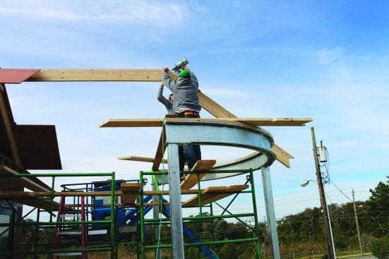
Like framing a hip roof, framing a cone (or in this case a half cone) begins with three common rafters. The first common rafter attaches to the end of the ridge.
Then the other two king commons support the ridge from the sides. They are 90 degrees to the ridge and to the other king common.
We ran a 2×10 ridge from the house over to where the semicircular framing of the porch began. In hip-roof fashion, we installed three king commons. The first ran in a straight line from the end of the ridge to the midpoint of the curved plate. The next two king commons opposed each other at the end of the ridge. These two rafters were perpendicular to the ridge and ran down to the beginning of the semicircle on either side.
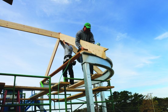
A tight intersection. With a hip roof, a hip rafter would extend 45 degrees out from the king-common intersection to the corner of the building. Because there was no corner, the rafters for this roof simply fanned out around the semicircle. I was concerned about the intersection where seventeen 2×8 rafters were all supposed to meet. I considered installing headers to catch some of the intermediate rafters, but a header would be a straight line between the radial rafters, with the top edge below the curved plane of the roof. In situations such as this, I find that the best strategy is making a full-size plan drawing of the roof to visualize the framing.
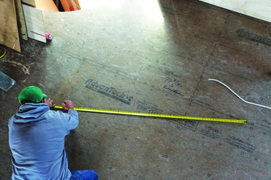
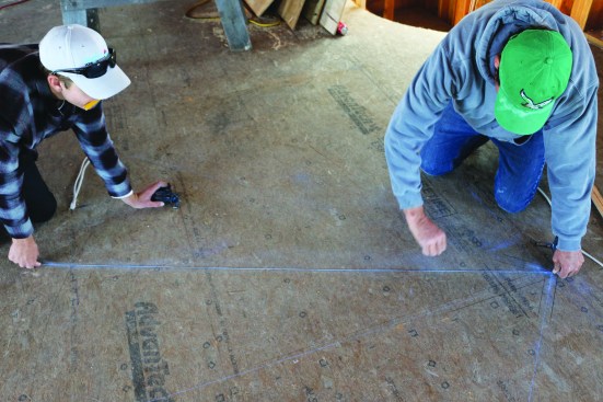
A full-scale plan drawing allows the crew to visualize the how the radial rafters intersect at the peak. A semicircle is swung to represent the top plate.
A ripping of 2-by material is used to trace the rafters one by one.
Full-scale drawing. With the house still in its early framing stages, we picked out a large open floor area for the drawing. After picking a center point for the semicircle (the center point of the end of the ridge), we drew its outer circumference and snapped centerlines for the three king common rafters. Using a straight ripping of 2-by material, we drew the outlines of the kings, which divided the half circle into two quarters of a circle. Next, we found the center point between the kings and drew in the rafters that broke the semicircle into eighths of a circle, then sixteenths, and finally thirty-seconds. That layout put the rafter tails just under 16 inches apart.
The crew darkens the rafter lines so that they can see the cut details where they intersect at the ridge.
So far, we’d let all the lines intersect at the top, but now I darkened in the ends of the rafters starting with the kings. The “eighth” rafters were followed by the “sixteenth” rafters. The acute angle at the end of the “sixteenth” rafters would be greater than 45 degrees, but we could still cut it with a circular saw. I decided just to butt the “thirty-second” rafters into the available spaces rather than trying to cut long tapered ends. Darkening in the ends of the rafters at the intersection also allowed us to take the cut angles directly from the full-scale drawing.
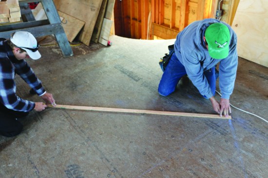
The side king common and the end king common create a quarter circle. The next task is dividing the quarter circle into eighths. To find the midpoint between the commons, the crew spans between them with a 2×6 and marks the midpoint. Then they transfer that point to the plate and mark the positions of the “eighth” rafters.
Plate layout. The tail ends of all the rafters in the semicircle would be identical, but before cutting, we needed to lay out the rafter positions on the plate. Typically, rafter layout on a straight plate means pulling a tape down the length, marking the rafter positions, and squaring the marks by holding the edge of the square against the plate. But with the curved plate, we couldn’t just “pull” the layout, and we couldn’t hold a square to the edge of the plate to mark the positions. Instead, we kept dividing the space between the king commons in half until we got the layout we needed.
Next they use the 2×6 to span between the eighth point and the common. The midpoint of that distance transfers to the plate as the position of the sixteenth rafters.
They mark the positions of the “sixteenth” rafters on the plate.
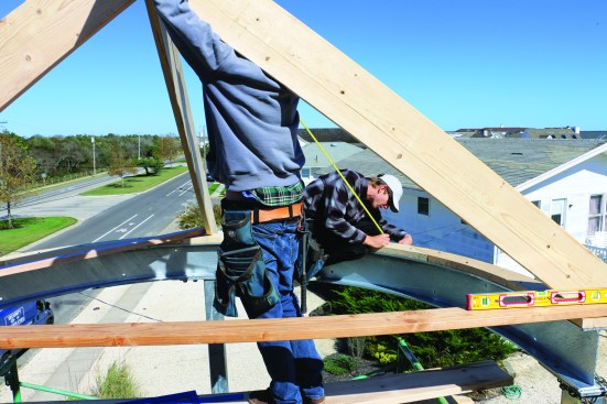
After laying out the rafters, the crew measures from the plate to the shoulder of the angled cut to find the length of each rafter.
We cut a 2-by to exactly span the quarter circle between the king commons, marked the midpoint on the 2-by, and squared over from that point onto the plate for the “eighth” rafters. After laying out their positions, we measured between that layout and the king common and transferred the measurement to the 2-by. Then we used the 2-by to measure and mark the positions of “sixteenth” rafters. Those rafters were close enough together that we just measured to the midpoint for the position of the “thirty-second” rafters.
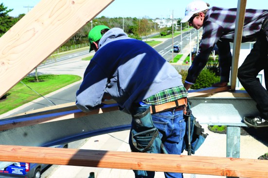
Rafters in the round. With the plates laid out, it was time to cut and fit the rafters. We measured from the outside edge of the plate to the shoulder position of the “eighth” rafters. We laid out and cut the rafter tails using the pattern rafter set aside earlier to mark the eaves overhang and the birdsmouth. Then we measured up for the plumb cut. Taking the angle from the floor layout, we set the saw blade angle and made the plumb cut at the top ends of the rafters.
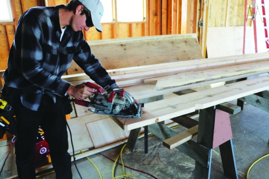
The rafter tails for the radial rafters are identical to the king commons, so the crew uses the pattern rafter to trace the tail before cutting the details.
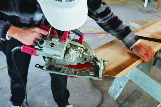
After measuring and marking the shoulders of the plumb cut, the crew member takes the saw angle from the floor drawing and cuts the top.
After cutting and installing the “eighth” rafters, we turned to the “sixteenth” rafters. We measured and cut them in the same fashion, but this time the acute angle made the cut a bit more challenging.
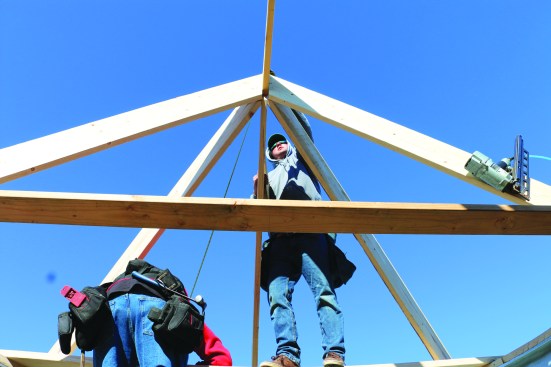
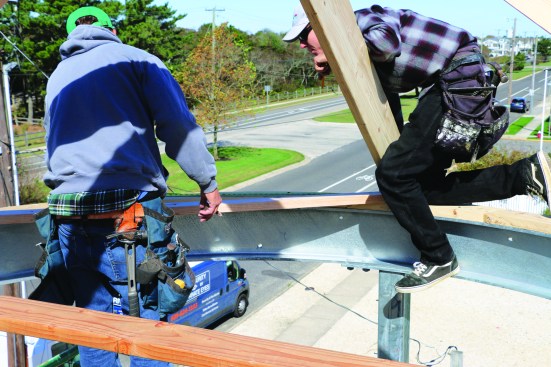
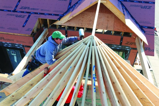
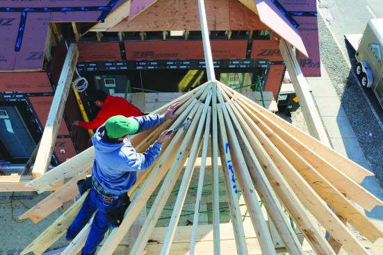
Starting at one end of the semicircle, the crew installs the rafters that divide the arc into eighths and then into sixteenths.
Finally, the crew installs the rafters that divide the sixteenth spaces into “thirty-second” spaces. Instead of trying to cut a long point at the top end of the thirty-second rafters, the crew butt-cuts the tops and toenails them into place.
Instead of installing all of the “sixteenth” rafters, we started at one side of the semicircle, installing the “sixteenth” rafters and filling in the “thirty-second” rafters while we were still in position.
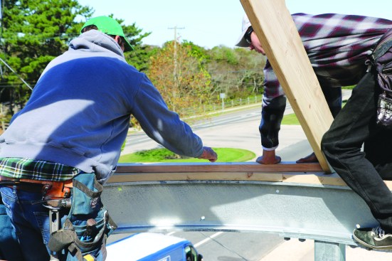
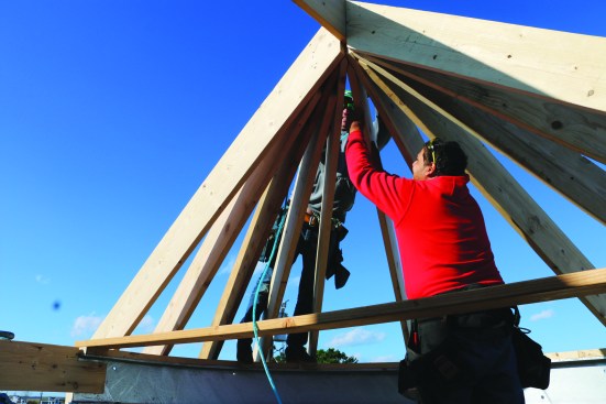
A crew member nails the tops of the rafters at the peak …
… and taps down any uneven rafters to put them in the same conical plane.
To join the rafters at the top of the cone, we toenailed or face-nailed wherever possible. When all the radial rafters were installed, I went around and made sure they were all in plane for the sheathing and trim, tapping them down where necessary.
Photos by Nathaniel Eldon