Our company regularly performs structural repairs on 19th- and early 20th-century residential brick buildings in the Chicago area. This one was a three-story, 60-unit apartment building with wood-framed partition walls and floors and a nearly flat and severely underframed roof. The 2×10 joists, running front to back, didn’t need to sag much before they were bearing on 2×4 ceiling joists. The partition walls beneath this ceiling were only meant to hold up plaster and lath but had become bearing walls supporting roof loads. The added live and dead loads transferred all the way to the first-floor joists, which had zero support under them and, over the years, had been cut up by previous contractors.
1
of 4
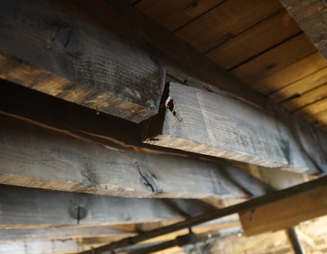
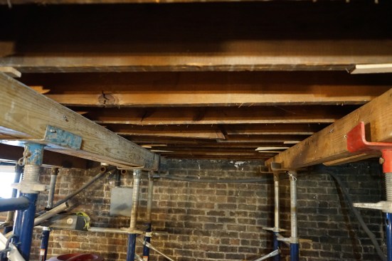
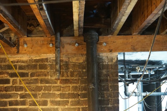
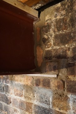
A partition wall, which sits directly above these damaged first-…
A partition wall, which sits directly above these damaged first-floor joists, was not designed to bear the added loads imposed by an underbuilt roof. … (see next two photos)
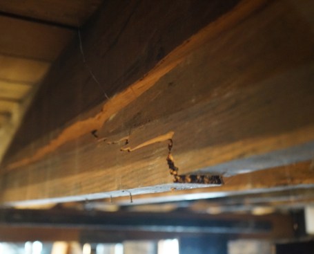
… Another damaged floor joist …
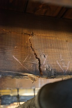
… and another damaged floor joist.
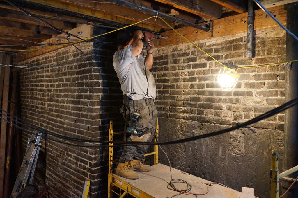
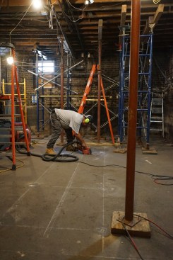
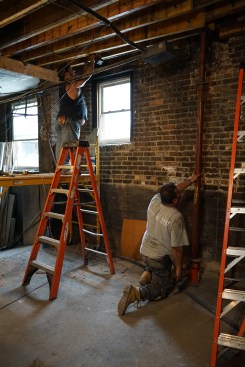
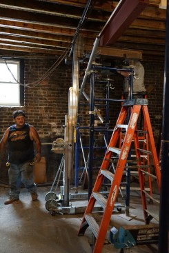
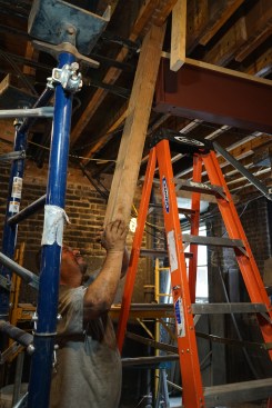
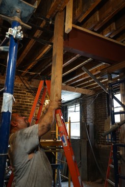
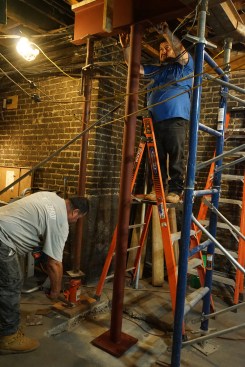
To begin repairs, the crew erected emergency shoring on each sid…
To begin repairs, the crew erected emergency shoring on each side of where a steel beam will be placed to support the load-bearing wall.
You can see the extent of the damage this caused in the slideshow above . Most of the joists directly below a full-height partition wall at midspan had failed, with many joists splitting along the centerline. The failure was especially noticeable at knots and other defects, which create a weak link in the lumber.
The magnitude of these failures prompted our first step: erecting emergency shoring. The occupants in the three apartments above were moved out and all the plumbing and electrical lines running through the floor were removed.
1
of 3
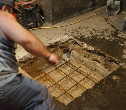
With the shoring in place, the crew cuts open the basement slab …
With the shoring in place, the crew cuts open the basement slab to dig 36-by-36-by-18-inch footings for columns to support the new steel I-beam.
Chairs —called “bolsters” in the Midwest—keep the rebar …
Chairs —called “bolsters” in the Midwest—keep the rebar grid in the footing elevated, allowing concrete to flow up to the rebar. Rebar is used to add tension strength to the concrete, and is placed in the bottom section of the footing where the tension forces will be greatest when the column is loaded.
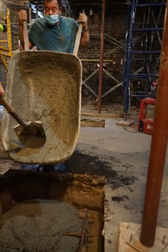
A worker pours concrete from a wheelbarrow into the hole in the …
A worker pours concrete from a wheelbarrow into the hole in the slab.
Working to engineered specs, we began our repair work by digging and pouring footings for steel posts to support an I-beam that would provide the necessary support for the wall above.
1
of 7
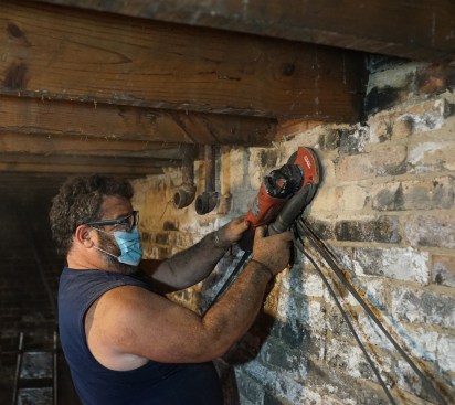
Toby Bonilla grinds down the high spots on the basement wall in …
Toby Bonilla grinds down the high spots on the basement wall in preparation for installing an LVL ledger.
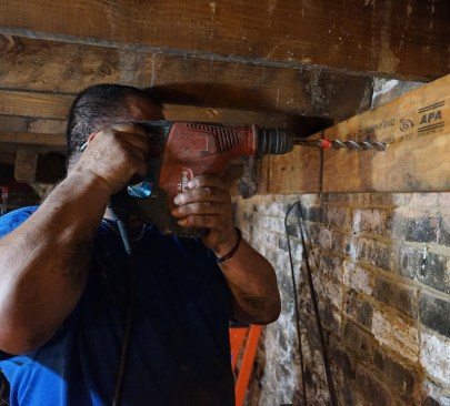
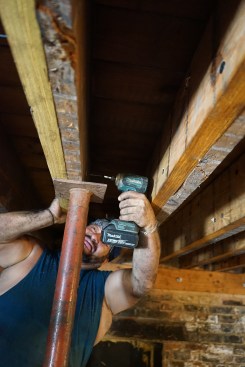
He drills through the ledger into the foundation wall to prep fo…
He drills through the ledger into the foundation wall to prep for epoxy anchors.
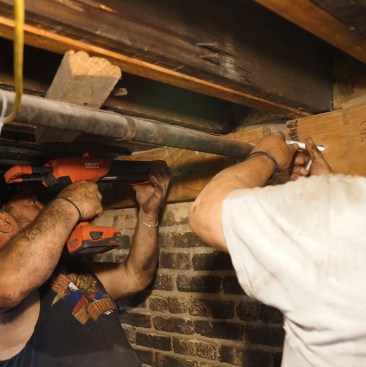
Toby and his brother Ernesto inject epoxy, and set the threaded…
Toby and his brother Ernesto inject epoxy, and set the threaded rod.
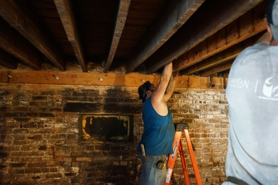
Working together, Toby and Ernesto Bonilla sister new LVLs to th…
Working together, Toby and Ernesto Bonilla sister new LVLs to the existing joists.
At one end, new LVL sisters rest on the LVL ledger.
With one end of the LVL sister bearing on a beam or ledger, the …
With one end of the LVL sister bearing on a beam or ledger, the opposite end is jacked up to align with the bottom of the existing joist.
Working from both sides of the assembly, Toby fastens a new LVL …
Working from both sides of the assembly, Toby fastens a new LVL with structural screws.
Before installing this beam, we secured an LVL ledger to the basement walls to provide extra bearing at the joist ends and sistered 1 3/4-inch-thick LVLs to the joists. These LVLs ran slightly past the midspan where the beam would go, and on each side of the beam, we staggered the LVLs on different faces of the failing joists to increase the bearing.
1
of 11
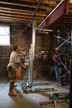
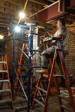
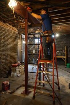
Because space was limited, the new steel beam had to be lifted i…
Because space was limited, the new steel beam had to be lifted in two sections, using a Sumner material lift.
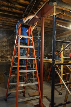
With the lift holding the first section in place, shoring is ere…
With the lift holding the first section in place, shoring is erected below the beam. At this stage, the beam is slightly low to allow the crew to move it laterally into a beam pocket in the far wall of the basement.
Prying against a joist pushes the first beam section into the po…
Prying against a joist pushes the first beam section into the pocket.
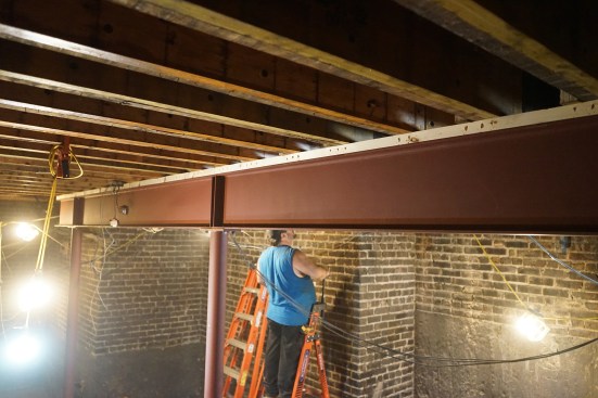
The beam slides into the pocket.
Grouted into the wall after the columns were set, the beam bears…
Grouted into the wall after the columns were set, the beam bears on a steel plate. Note the top plate on the beam installed with powder-actuated fasteners prior to lifting.
The second beam section is lifted into place and shoring erected…
The second beam section is lifted into place and shoring erected to safely support it.
Ernesto jacks the beam, while Toby eyes a level.
The author bolts the top of the steel columns to the bottom flan…
The author bolts the top of the steel columns to the bottom flange of the beam.
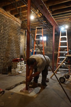
The columns are sized to allow a steel shim to slip below the ba…
The columns are sized to allow a steel shim to slip below the base; non-shrinking grout is added below each base before it is bolted down with Simpson Titan HDs.
The author toenails through the nailer on the beam into the jois…
The author toenails through the nailer on the beam into the joists to keep them from rotating.
The far end of the second beam cantilevers beyond the far column…
The far end of the second beam cantilevers beyond the far column. Above each column, stiffening plates have been applied by the beam fabricator to ensure loads transfer to the column.
With the LVL sisters in place and raised in line with the bottom of the floor joists, we could install the beam and post down to our footings. The photos and captions in the slideshows here describe the sequence of steps needed accomplish the critical steps in this repair.
JLC contributing editor Jake Lewandowski is a construction manager with his family’s business, Great Lakes Builders (greatlakesbuildersinc.com), which specializes in structural repairs in Greater Chicago. Follow him on Instagram: @jakemlewandowski