
Most people will tell you that the secret to a good open floor plan is to define room spaces without interrupting sightlines. That’s the concept behind a trim detail we completed on a recent remodel job. While open floor plans might seem like a hot new trend, room dividers aren’t; if you are a fan of historic homes, you probably have seen variations on the trim detail described in this article.
A Classic Design
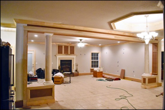
The home had a large living room with a couple of large bookcases capped with a short end wall that defined the room. To open up the space, we removed the bookcases, but our client still wanted some kind of architectural feature that would help signal where the foyer ended and the living room began. He was open to suggestions, so I shared several pictures from my design album that I had saved over the years, and it didn’t take long for him to pick one—which I think of as a classic room divider—as the inspiration for our design.
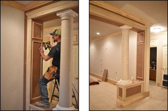
Fortunately, the room had 9-foot ceilings. I have seen versions of this detail in bungalows with 8-foot ceilings, but it’s tricky to make the proportions work out with a standard ceiling height. In our interpretation of the detail, we build a false beam across the ceiling and two short paneled wall sections on either end to serve as pedestals for a pair of 12-inch round columns. These trim details are almost always painted, which helped a lot on this project because it allowed us to use fiberglass columns and a healthy mix of MDF stock, poplar trim, and finger-jointed moldings to build the beam, pilasters, and paneled walls.
Structurally, there was a large LVL beam in the attic that carried the ceiling joists and some roof bracing. The two short walls we removed didn’t carry much of the beam load, but to prevent any settling, we supported the beam with a temporary 2-by post until we placed the round columns. I planned to reinforce the beam above the column locations with solid blocking and to install vertical 2-by legs under each column as we built the new wall sections.
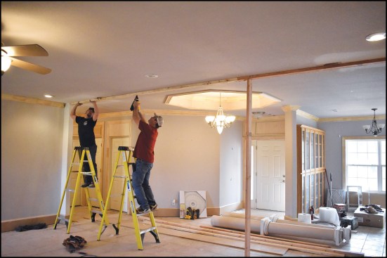
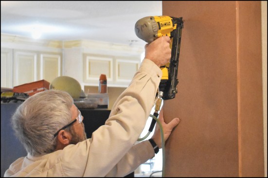
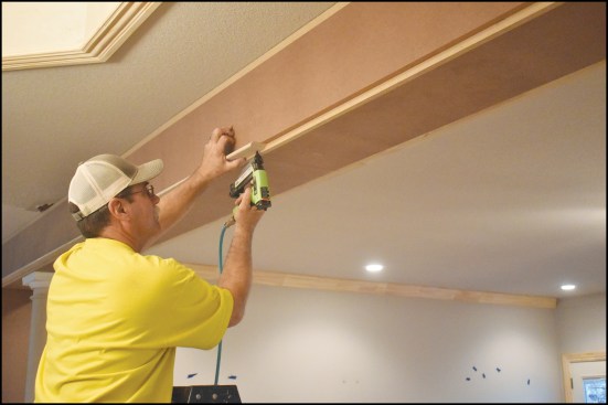
The crew began by fastening 2×4 cleats to the ceiling directly underneath an LVL beam that supports the second-story floor framing.
Building the Beam
Working from the design in my inspiration photo, which showed a beam wider than the column capitals, we started by snapping a pair of chalk lines on the ceiling 12 inches apart and nailing 2x4s to the lines. Instead of removing long pieces of existing crown molding to accommodate the new beam, we used a multi-tool to cut out just the areas of crown that were in our way.
The room was more than 16 feet wide, so each part of the beam required a splice. When nailing up the MDF sides of the beam, we used just enough fasteners to hold them in place, then sighted down the entire beam to make sure the sides were straight. If you don’t trust your eye, you might want to pull a string, but most good trim carpenters can see any adjustments that need to be made to keep the pieces aligned. We just made a simple butt splice, but each joint is backed by a 6×10 piece of MDF fastened with glue and brad nails.
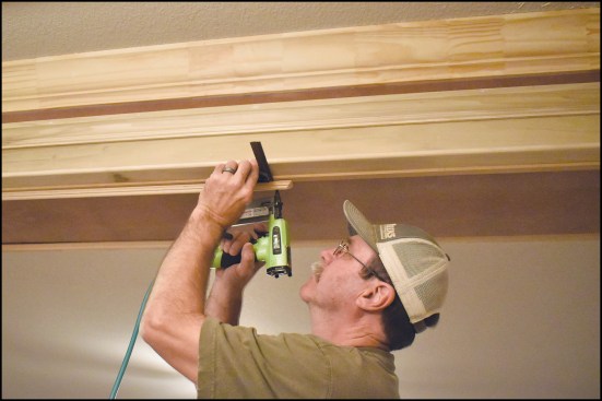
At each end of the beam—directly above the future column location—we stacked 2×4 blocks. The trick is to make sure the blocks are stacked plumb or even slightly leaning in (easy to shim out to plumb, but impossible to correct if the blocks bow out). We also added stacks of 2-by blocks every 3 feet across the length of the beam to make it rigid.
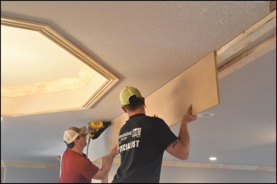
After tacking MDF sides to the cleats (above) …
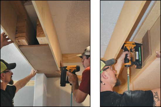
… the crew added stacks of blocking (above left) as they continued to build out the false beam. MDF cleats were tacked and brad-nailed to reinforce the spliced butt joints (above right).
I needed to add a solid shim between the 2×4 blocks and the beam bottom to make sure that any loads from above would be transferred down to the round columns, so we spliced the beam bottom just beyond each column. Then we installed a solid lumber shim that had been carefully planed down for a tight fit. It added a splice, but I didn’t want there to be any chance the beam would bow under load. To attach the rest of the beam bottom, we added short nailer blocks, using a scrap of MDF as a gauge block as we went.
Pilasters and Short Walls
The round columns would sit at the ends of short paneled wall sections, but first I had to build a pair of full-height flat pilasters, one at each end of the beam right at the wall. I started by drawing plumb lines down from the beam ends, then added blocking as needed at the top and bottom and along the wall. I built the flat pilasters out of MDF ripped to width and nailed to the wall.
The author fastened an MDF panel to the wall underneath each beam end, building out the pilaster detail with short MDF returns as needed.
Next, I ripped stiles and rails to width from S4S poplar and cut MDF panels from 3/4-inch-thick sheet stock. Then I used pocket screws to assemble the four frame-and-panel sections and the two end-cap panels for the short walls.
After setting the short wall panels in place, we added MDF tops, and PT plates between the panels. To make sure loads from the beam were transferred to the slab, we added three vertical 2-by blocks under each column location before installing the end caps.
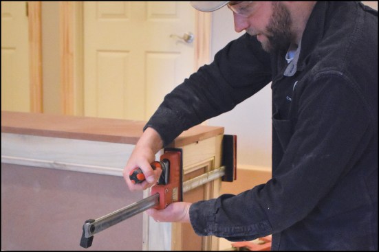
To make seamless joints in the assembled pilasters, I used a four-step process. First, I applied a generous amount of wood glue to the joints. Then, after positioning the pieces, I tacked the joints together with a headless 23-gauge pinner, to keep the pieces aligned. Next, I clamped the joint together until glue started to squeeze out. After about an hour, I removed the bar clamps and sanded the joints smooth with a small random orbit sander.
Wrapping the MDF tops with panel molding and the wall bases with baseboard finished off the short-wall detail.
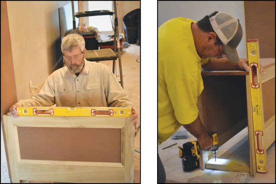
Then he assembled four frame-and-panel sections with pocket screws for the short walls (above left). After PT plates (above right) …
… and vertical 2×4 blocking were added to support the columns, the end panels were glued, pinned, and clamped into position.
Fiberglass Columns
After making sure there was solid blocking inside the beam and the wall below, now I had to carefully measure and cut the fiberglass columns to fit snugly between the two. Cleanly and accurately cutting a round post can be challenging, but I’ve always had good success bending a thin wood ripping around the column to mark the cut line. I don’t typically cut fiberglass columns using my best saw blade; they cut well enough with a good carbide-tipped blade.
These columns were tapered, so I marked the centers of the capital and base and then used a long level to plumb the columns up in both directions during installation. To attach column capitals and bases, we typically use long trim-head screws, in addition to a little construction adhesive.
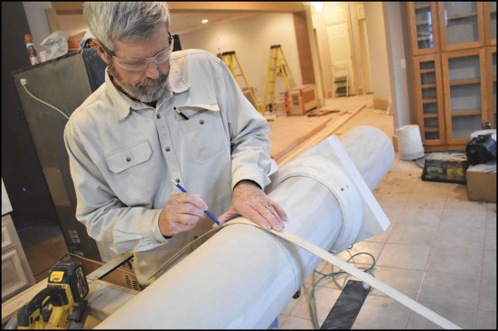
The author used a flexible wood batten to mark the cut lines on the round columns (above).
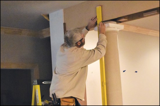
To help ensure that the tapered columns were installed plumb, he used a spirit level to align the centerlines that he marked on the columns’ capitals and bases.
Trim Details
With the columns installed, we returned to finishing up the beam by filling in the remaining bottom pieces. To match the design in our inspiration photo, we ended up almost totally covering up the basic beam with multiple layers of trim, starting with a wide band of MDF held one inch up from the beam bottom.
The rest of the trim detail resembles a header detail we often use on windows and doors. We started by adding a 1/2-inch-thick-by-2-inch-wide site-made bead detail under the MDF band, then stacked a 3/4-inch-by-5-inch strip of poplar above the bead. The final piece of the header detail is a 1-inch by 2-inch-tall panel molding with a crown-like profile. A small crown or bed mold would work here too, but I like the solid top of this molding. Before we put away the stepladders, we finished running the finger-jointed crown molding around the room.
A number of different elements were used to trim out the false beam, starting with another wide MDF band applied to the sides of the beam, followed by a 1/2-inch-by-2-inch bead (above)…
… and other panel and crown molding profiles.
I was starting to get excited about how the project was looking, but I could see two places that needed a little more attention. We added frames made of a small panel molding to the flat pilasters at the wall. The joint between the beam sides and bottom had only been nailed. I didn’t have enough clamps to do the whole joint at once, so we added a small clover-leaf molding instead of trying to make a perfect joint with glue and clamps.
The room divider is the first thing anyone coming in the front door sees. Before the painter even got to the job, we were getting compliments from everyone who stopped by. It looked like it was part of the original trim package. Most important of all, my client absolutely loves it.
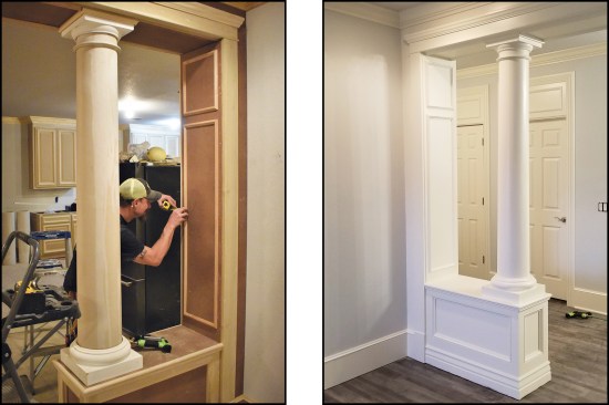
Panel molding was also used to create the simple frame-and-panel detail on the pilasters (above left). The painted assembly (above right).
The classic room divider helps define the transition between the entry foyer and the living room.
Photos by Gary Striegler and Mark Gannaway.
Got a Comment?
Click here to submit a Letter to the Editor. We value all comments, corrections and questions.
If we think others will benefit, we may publish it in print. Letters should be exclusive to JLC, Professional Deck Builder or Tools of the Trade. We do not publish open letters or third-party letters. Writers of letters selected for publication will be notified. Letters may be edited for clarity and shortened for space.