Last fall, JLC went to the jobsite on Peaks Island where lead carpenter Mark Pollard and the crew of Thompson Johnson Woodworks were building the foundation for one of the company’s most challenging jobs to date: an architect-designed custom home with enough odd angles to puzzle Pythagorus (see “Customizing an ICF Foundation,” Nov/16).
Unique as it was, that foundation has not been the toughest problem this custom project has thrown at the Thompson Johnson team. Wall framing, involving a wood I-joist buildout for superinsulation as well as a two-story corner window, brought its own head-scratchers. And then came the roof (the topic of this story).
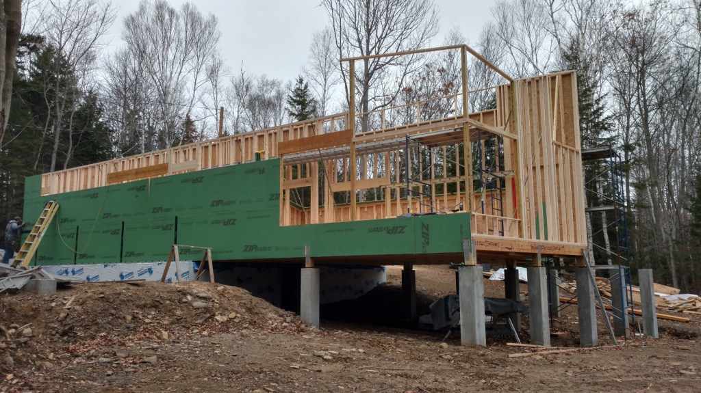
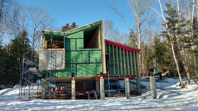
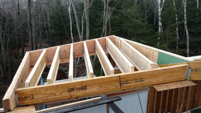
To make the most of a gently sloping clearing that borders on woods, Portland architects Kaplan and Thompson devised a highly original form. The largest element in the house (shown during framing) is a long, parallelogram-shaped main room with a two-story vaulted space at the downhill end. This long room has a monopitch shed roof, with one major wrinkle: Rising up at one corner of the roof is the upper portion of a tall, two-story corner window wall, which, for lack of a better term, the construction crew is calling “a dormer.” But this is no ordinary doghouse dormer. It’s really more of a boxy shaft that thrusts through the main shed roof, and it’s topped with its own shed roof that pitches on two axes, forming a shallow valley with the main roof.
It’s topped with its own shed roof that pitches on two axes, forming a shallow valley with the main roof.
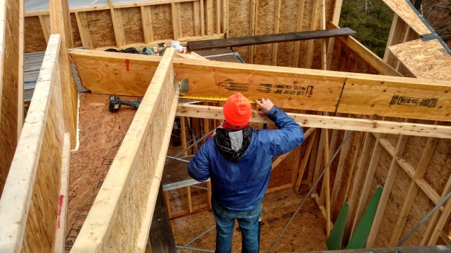
Visualizing the shape. The custom-designed windows specified for this end of the house aren’t square at the top, but instead have one corner higher than the other. And at the wall-to-ceiling joint, says Pollard, the plans call for no window casing: “The drywall on the ceiling just dies right into the top of that window, without any step-down.” So Pollard took his layout for the roof assembly from the shop drawings for the upper corner windows. “I just drew a full-scale drawing on the subfloor,” he says. Then he framed a skeleton shape with 2x4s to guide the placement of massive LVL headers to support the roof frame. This skeleton outline would also determine the plane of the vaulted room’s ceiling.
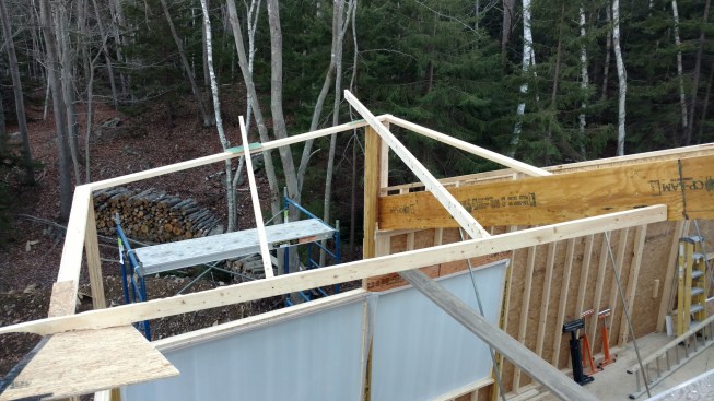
The custom-designed windows specified for this end of the house aren’t square at the top, but instead have one corner higher than the other and no window casing.
Beams and a Flush Ceiling
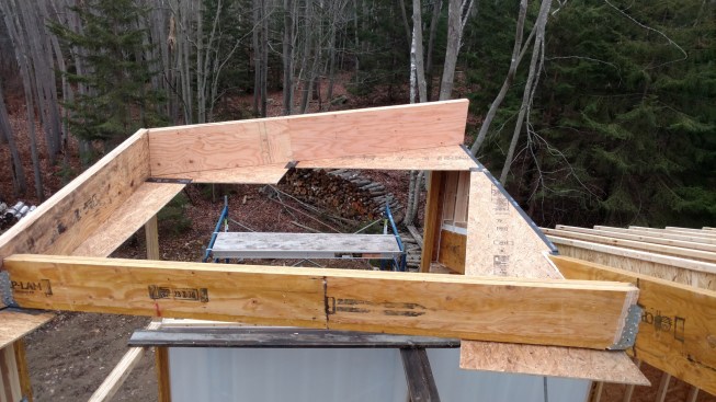
This custom home is aiming for Passive House energy performance, and for health reasons, the clients also need indoor relative humidity maintained at 50% year-round. For airtightness and calibrated vapor control, the designers opted to sheathe the underside of the ceiling with Huber Zip System sheathing (with the membrane side facing down) and tape the seams with Zip tape. So once the 2×4 skeleton of the room was in place, Pollard went ahead and installed Zip System panels around the perimeter of the shape (see photos, above). The panels defined the plane of the ceiling, even before the perimeter beams and low-slope I-joist roof rafters were installed.
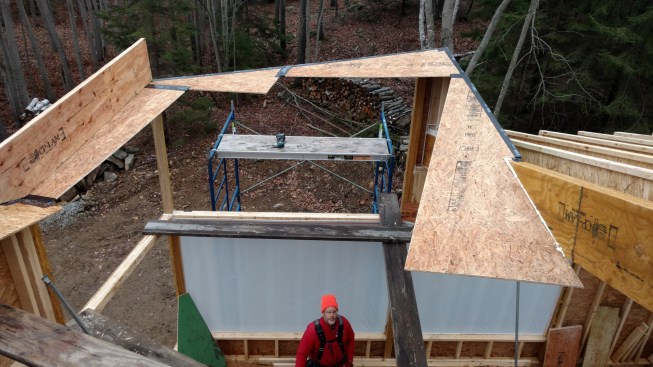
The crew set pie-shaped pieces of Zip System sheathing in place on the skeleton outline of the window-wall structure.
If the pie shapes of the panels and the zig-zag pattern they form look peculiar, it’s because the crew laid out and cut the panel shapes in anticipation of the roof framing that would follow. Says Pollard: “Those pieces of Zip panel were cut that way so that they would be square to the rafters, so that eventually when we were all done framing the roof, we could go back, and we would not have to cut weird polygon shapes to infill the rest of the Zip on the ceiling. The edges are cut to fall out at the midline of the rafters when the rafters are placed.”
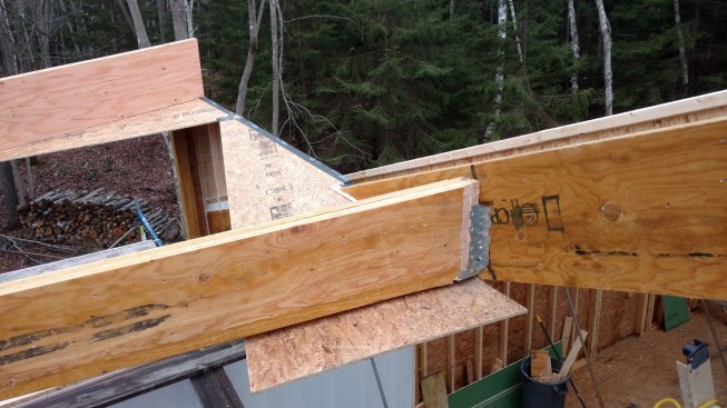
Next the crew had to set structural beams around the perimeter of the room, forming a sort of hybrid between a window header and a structural rim joist—but intended to support not floor joists but low-slope I-joist rafters. They also needed to set a structural valley rafter at the intersection between the main building’s shed roof and the counter-sloping roof of the window-wall room. For this valley rafter, Pollard explains, Portland engineers Casco Bay Engineering originally specified a single 16-inch-deep LVL. At the uphill end of the valley, the original plan was to tie the valley rafter into a doubled-up 16-inch LVL common rafter.
“But we were concerned about thermal bridging at the valley,” says Pollard, “and the potential for ice to form there in the wintertime when there’s a lot of snow on the roof. So we asked the engineer to downsize the valley rafter, as well as the common rafter that it ties into at the uphill end.” The revised solution was a double 12-inch LVL valley rafter and a double 14-inch common rafter. The 16-inch I-joist jack rafters would sit proud of the valley beam by 4 inches, leaving room for blown cellulose insulation between the beam and the skin of the roof.
Connecting the valley rafter to its support beams at either end, and connecting the I-joist jack rafters to the wall header beams and the valley beam, posed a hardware problem: None of the connections were at right angles. For the I-joist rafters, however, there turned out to be an off-the-shelf solution. “It’s a Simpson Strong-Tie product called the LSSUH310—a ‘slopeable, skewable’ hanger,” says Pollard. “It has a bottom shoe that can pivot up and down for your roof slope, and two big wings on either side, where it gets nailed to the carrying beam, that you can bend in order to skew the rafter from side to side.” To connect the hangers to the beams, the crew used positive-placement gun nails—1 1/2-inch nails for fastening to single LVL timbers, and 3-inch nails where doubled-up LVLs provided enough meat for the longer nails.
The valley rafter, downsized to a 12-inch height to allow for insulation above it.
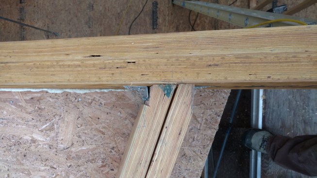
It had to be shaved at the ends.
This allowed for its out-of-square and out-of-level orientation with respect to the common rafter supporting it at the uphill end, and the wall header supporting it at the downhill end.
There was no comparable piece of hardware for the valley rafter, however—and it, too, had to connect at out-of-square angles to the LVLs supporting its ends. So the crew had to shave and bevel the rafter’s ends to fit into a conventional hanger.
The LVL rafters for the low-slope roof system were set out of square to the beams that they tied into.
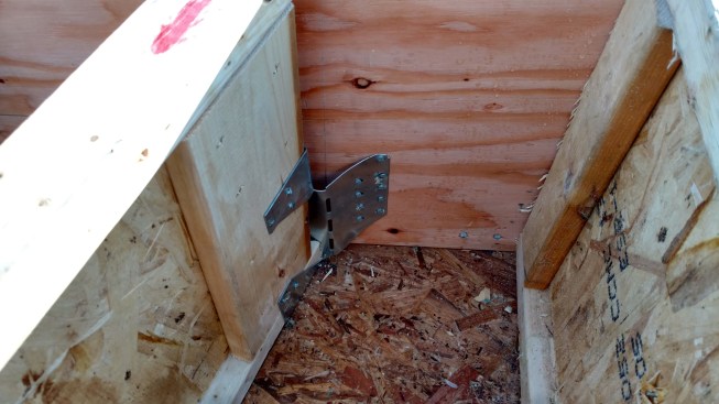
It required the use of “slopeable, skewable” structural connectors.
The bottom shoe of these hangers can pivot up and down, while the ears on the sides can be bent from side to side.
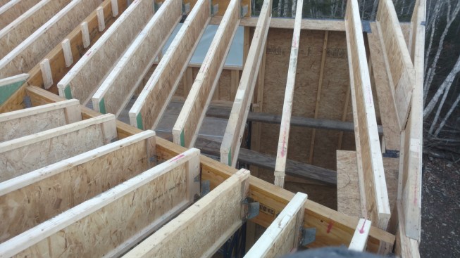
Where the I-joist rafters meet the doubled-up LVL valley rafter, the I-joists stand about 4 inches proud, leaving space for insulation above the valley member to reduce the risk of melting snow and formation of ice in winter.
Constructing the Vented Roof
A unique, low-pitch cathedralized roof wouldn’t be complete without an extra building-science challenge thrown in, and this building supplies one: As we mentioned, the home’s mechanical systems are designed to maintain interior relative humidity at a constant 50% because of the owners’ health requirements. So the superinsulated walls and ceilings have to be able to handle this condition, year round.
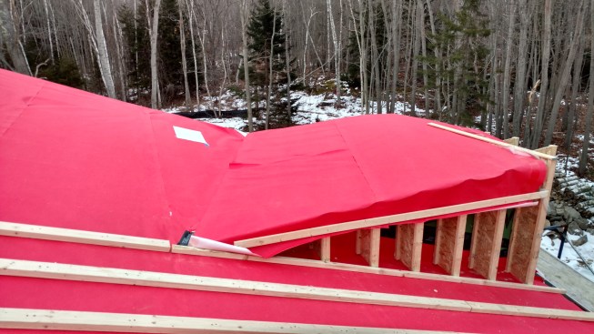
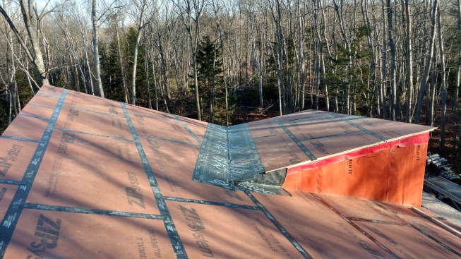
With the roof framing complete, the crew constructed a vented roof assembly. Vapor-open, water-resistive VaproShield SlopeShield roof membrane was attached to the rafters, and 2×4 furring laid on top of that.
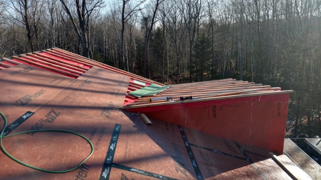
Then the crew sheathed over the furring with Zip System roof sheathing, sealing the seams with Zip tape and protecting the valley with Grace Ice & Water Shield.
The team got a thumbs-up from Portland mechanical engineer and Passive House consultant Sonia Barrantes for a cold-roof assembly with plywood sheathing on the rafters, 2×4 sleepers to create an air channel, and another layer of plywood for the roof deck. But in the end, they opted for a more vapor-open solution. They stretched VaproShield’s SlopeShield membrane (vaproshield.com) over the rafters, and nailed 2x4s through the membrane to create a venting space. Then they installed Zip System roof sheathing over the furring, sealing the seams with Zip tape and protecting the valley with Grace Ice & Water Shield.
The 16-inch I-joist rafter cavities would later be filled with dense-blown cellulose insulation.
Like other high-performance weather-barrier products on the market, VaproShield membranes are highly vapor-open. “But my big reason to prefer VaproShield was its Integrated Tape system,” says Pollard. “At the bottom of each roll of fabric, there’s tape on the back, and at the top, the tape is on the face. So as you shingle-lap the courses, you pull off the cellophane on the strips of tape, and the two faces bond together tenaciously—as opposed to other systems where you have to face-tape over the laps. I mean, those other systems have worked forever, and you know they’re going to work, but to me it just seems wrong to reverse-lap tape.”