
Conrad Geyser
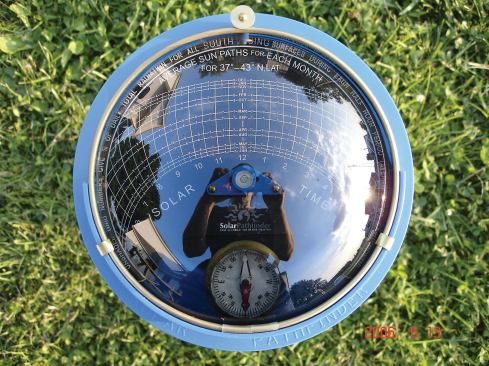
The author uses the Solar Pathfinder site-assessment tool to eva… The author uses the Solar Pathfinder site-assessment tool to evaluate the effect of local shading on a PV array. For optimum power output, the angle of a fixed photovoltaic array should equal the local latitude — about 42 degrees at this Massachusetts site.
Conrad Geyser
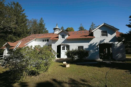
While the existing roof wasn’t a perfect match, it was close e… While the existing roof wasn’t a perfect match, it was close enough: PV panels are now cheap enough that it’s more cost-effective to install a larger array directly on the roof than to incur the additional cost of angled mounting brackets.
Conrad Geyser
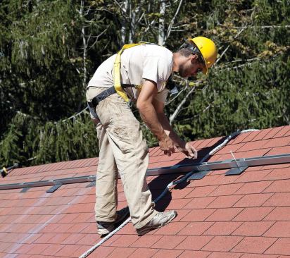
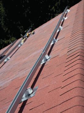
After snapping lines marking the position of the rafters, the in… After snapping lines marking the position of the rafters, the installer lays out the first extruded-aluminum mounting rails, which will be fastened to each rafter with a 5/16-inch hot-dipped lag screw.
Conrad Geyser
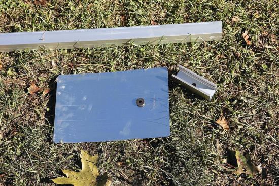
The rails are held off the roof at each connection by a short sp… The rails are held off the roof at each connection by a short spacer or “mounting foot” cut from extra railing material. A manufactured aluminum flashing tab is slipped under the shingle above; its rubber grommet forms a weatherproof seal around the lag.
Conrad Geyser
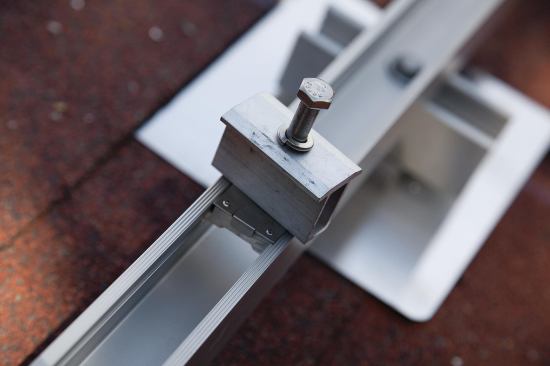
Where required, rail sections are joined between mounting feet w… Where required, rail sections are joined between mounting feet with splice fittings that allow for necessary thermal expansion and contraction. The fittings add enough flexibility to allow the rails to conform to minor irregularities in the roof plane.
Conrad Geyser
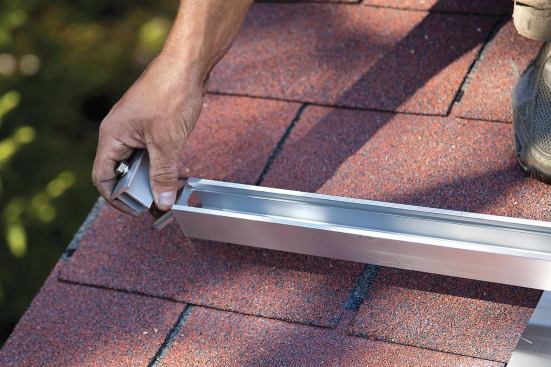
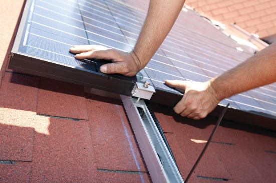
Intermodule clips are slipped into tracks as each rail is instal… Intermodule clips are slipped into tracks as each rail is installed.
Conrad Geyser
The clips fit between adjacent modules, securing them to the rai… The clips fit between adjacent modules, securing them to the rails and ensuring a consistent edge-to-edge spacing. Slightly different fittings are installed at the end of each rail.
Conrad Geyser
The modules will be grouped in two separate “strings,” so on… The modules will be grouped in two separate “strings,” so only two roof penetrations are required for the entire 38-module array. A waterproof plastic junction box at each penetration is carefully sealed to the shingles with silicone to prevent leaks.
Conrad Geyser
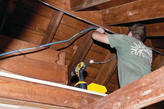
Two parallel runs of metal-clad cable conduct power from the roo… Two parallel runs of metal-clad cable conduct power from the rooftop array to the service entrance.
Conrad Geyser
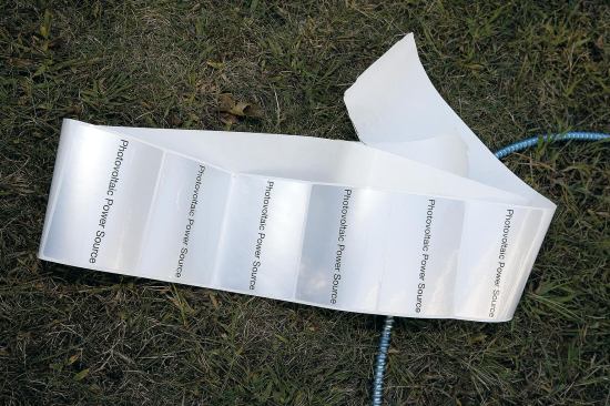
Adhesive stickers identifying the cable as a photovoltaic power … Adhesive stickers identifying the cable as a photovoltaic power source will be attached to the cable at regular intervals, as required by code.
Conrad Geyser
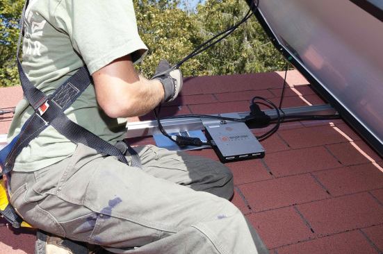
Each 245-watt PV module is given its own microinverter, which co… Each 245-watt PV module is given its own microinverter, which converts the DC output to AC and continuously adjusts the output for maximum wattage. The microinverters also enhance safety by shutting off the flow of power in case of a local outage on the grid.
Conrad Geyser
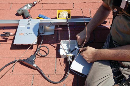
After manufactured module interconnection cables are laid out on… After manufactured module interconnection cables are laid out on the roof, a locking waterproof plug at each microinverter is snapped into the adjacent cable fitting, and the cable is connected to the metal-clad cable and module ground wires at the junction box.
Conrad Geyser
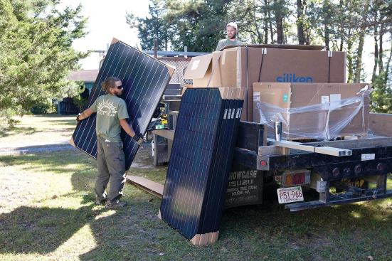
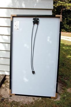
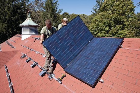
At about 65 inches by 40 inches and 42 pounds, individual module… At about 65 inches by 40 inches and 42 pounds, individual modules are easily handled by one worker.
Conrad Geyser
Each panel’s DC output passes through a pair of wire leads on … Each panel’s DC output passes through a pair of wire leads on the back.
Conrad Geyser
Starting at one end of the mounting rails, workers move modules … Starting at one end of the mounting rails, workers move modules into position and connect their positive and negative leads to the microinverter input fittings.
Conrad Geyser
Cables are zip-tied to the rails or module frames as needed to p… Cables are zip-tied to the rails or module frames as needed to prevent them from rubbing against the shingles or trapping debris.
Conrad Geyser
Another set of mounting clips is positioned against the outside … Another set of mounting clips is positioned against the outside edge of the module frame, and the sequence is repeated for the next module.
Conrad Geyser
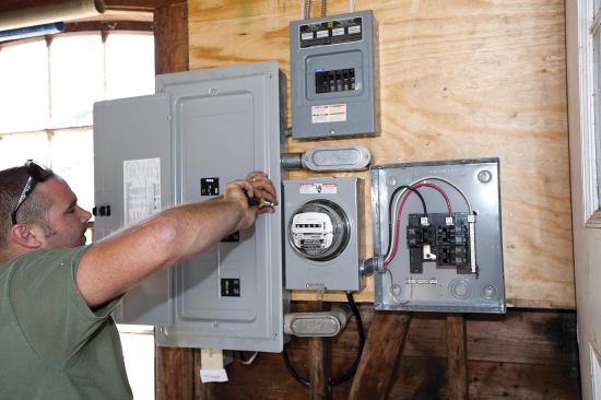
At the service entrance, the metal-clad cables from the array ca… At the service entrance, the metal-clad cables from the array can just be seen here entering the subpanel at top center. Because the power from the panels has already been converted to AC and synchronized with the grid at each microinverter, there’s no need for a large synchronous inverter between the PV subpanel and main breaker box at far left. The utility-grade meter at center tracks the array’s power production. The additional box to the right of the meter will contain a data acquisition system, or DAS, which will automatically track production of solar renewable energy credits (SRECs) and send that information to a third-party meter reader.
Conrad Geyser
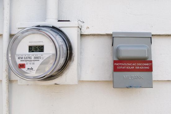
A second meter on the outside wall registers the homeowner’s n… A second meter on the outside wall registers the homeowner’s net power use, spinning forward or backward depending on whether the home is drawing power from the grid or supplying it. If more power is produced than used, there’s no electric bill that month. A utility-required emergency shutoff switch allows utility workers to confirm that the panels are offline when needed.
Conrad Geyser
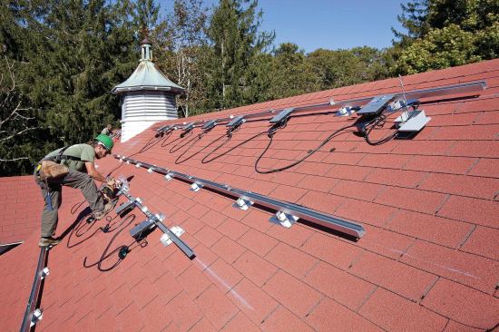
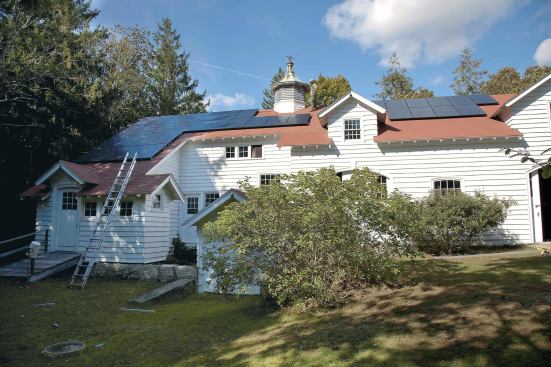
Layout of the 9.3-kw array (two additional PV modules lie on the… Layout of the 9.3-kw array (two additional PV modules lie on the far side of the larger gable dormer at right) was based on a thorough shading analysis of the site. Because the structure faces southwest, it receives full sun relatively early in the day for much of the year, but is subject to some late-afternoon shade. (Several trees to the west of the array were later removed to eliminate some shading.)