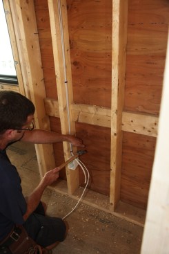
Flipping a light switch and plugging something into a receptacle are things we do every day without a second thought. Most of us can’t recall a time when electricity was not an integral part of our lives. But few people realize how much work goes into making sure that everything behind those devices—inside the walls—is installed properly to deliver electricity for our needs. In the industry, that part of wiring is called “roughing in.”
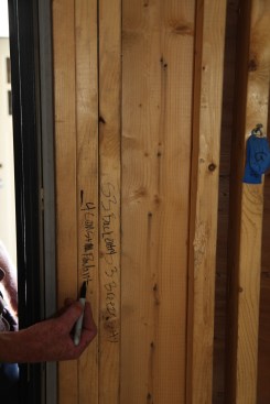
Before running cable, the author marks the location of every switch and notes what that switch will control. He also indicates if a switch is a 3- or 4-way.
A circle with two lines indicates a receptacle location.
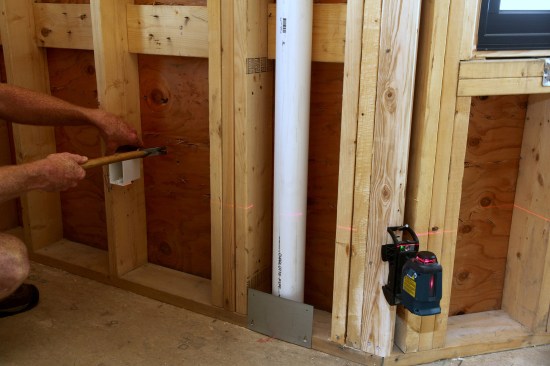
To keep all of the receptacle boxes at the same level, the crew sets up a laser level. They then align the bottom of the box to the laser line before nailing the box in place.
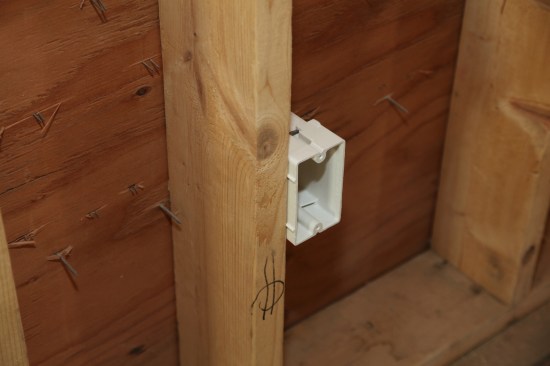
Small plastic nubs on the sides of the electrical box sets it at the proper depth for the drywall.
1
of 5
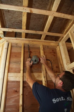
The author drills a 3/4-inch-diameter hole (big enough for a max…
The author drills a 3/4-inch-diameter hole (big enough for a maximum of two cables) through the plates and into a joist bay.
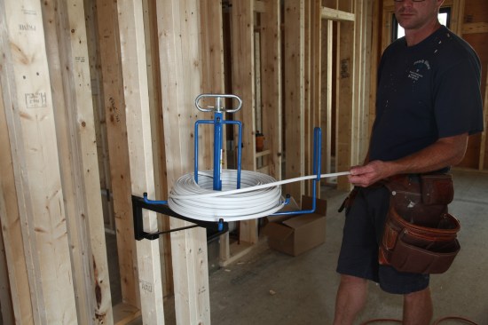
A spooler mounted on a wall stud keeps the cable straight and fl…
A spooler mounted on a wall stud keeps the cable straight and flat as it comes off the roll.
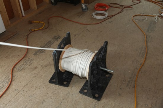
Cable often comes in large spools, and can be dispensed directly…
Cable often comes in large spools, and can be dispensed directly from the spool mounted on an axle between two factory-made brackets.
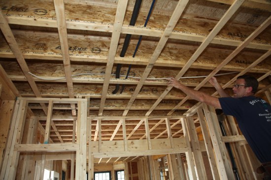
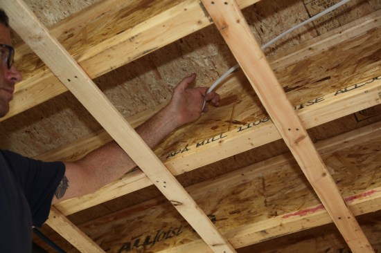
Taking care to keep the cable flat with no twists, the author fe…
Taking care to keep the cable flat with no twists, the author feeds a length of cable through a joist bay.
Roe Osborn
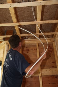
To keep the cable flat and without a twist, the author makes a l…
To keep the cable flat and without a twist, the author makes a large gentle loop in the cable as he feeds it through the hole drilled in the plates.
1
of 8
To staple a run of cable to the side of a joist, the author firs…
To staple a run of cable to the side of a joist, the author first hooks the cable with one finger and flattens the cable against the joist with the side of his hand.
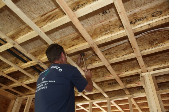
While holding the cable flat, he drives a cable staple about thr…
While holding the cable flat, he drives a cable staple about three-quarters of the way in.
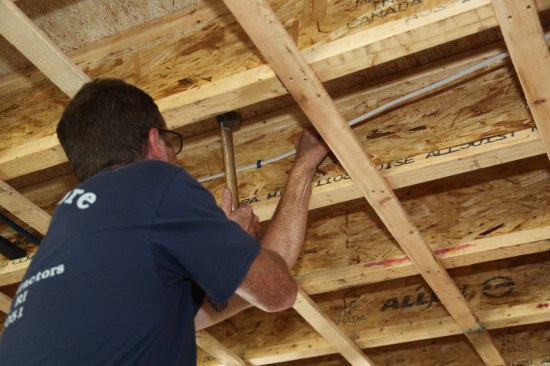
Then he reaches over and pulls the cable
tight while he finishes…
Then he reaches over and pulls the cable
tight while he finishes driving the staple into the joist.
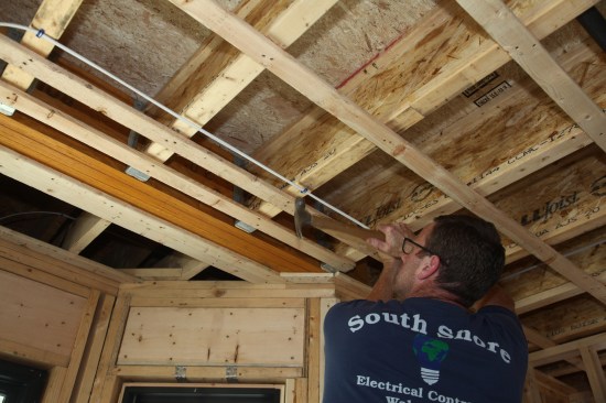
Strapped ceilings allow cable to run perpendicular to the joists…
Strapped ceilings allow cable to run perpendicular to the joists if the cable is kept a minimum of 2 inches from the strapping. Otherwise the cable would be have to be fed through holes drilled in the joists.
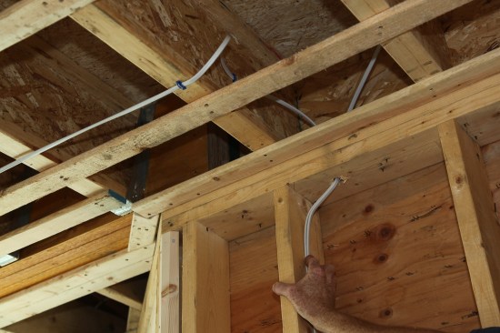
When changing the cable’s direction—from perpendicular to th…
When changing the cable’s direction—from perpendicular to the joists to parallel, or from a horizontal run to a vertical run—the author makes a wide gentle loop to keep the cable flat and relaxed. A staple secures the cable at both sides of the transition.
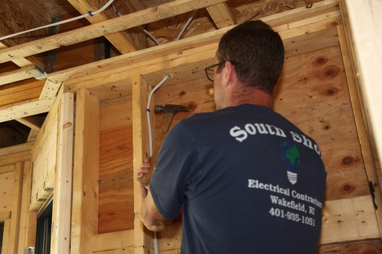
In a stud bay, the author drives the first staple about 6 inches…
In a stud bay, the author drives the first staple about 6 inches down from the plate again keeping the cable relaxed in the transition from the drilled hole.
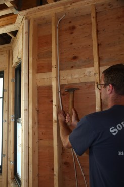
Working down the stud, the author drives staples every few feet,…
Working down the stud, the author drives staples every few feet, pulling the cables tight as he moves along.
A staple just above the electrical box holds the cables before t…
A staple just above the electrical box holds the cables before they are fed into the box.
1
of 11
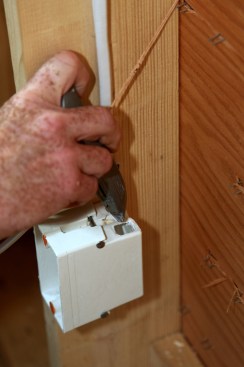
The author uses a the blunt end of a utility knife to remove the…
The author uses a the blunt end of a utility knife to remove the knock outs in the box for the two cables.
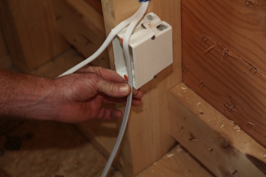
The author will loop the cables before they enter the box. To ga…
The author will loop the cables before they enter the box. To gauge where to begin stripping off the outer jacket he grips the cable at the bottom of the box with a finger and thumb.
Starting just below his thumb the author carefully slits the out…
Starting just below his thumb the author carefully slits the outer jacket of the cable with a utility knife. For the second cable the author begins the slit about 1 inch farther down.
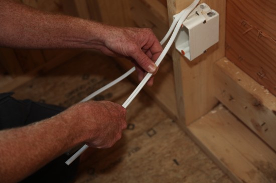
After both cables have been stripped, the author feeds the first…
After both cables have been stripped, the author feeds the first cable into the box in a loop. The loop gives the crew extra length in case one of the connectors gets damaged during drywalling.
After both cables have been fed into the box, the ground conduct…
After both cables have been fed into the box, the ground conductors are separated fron the other conductors.
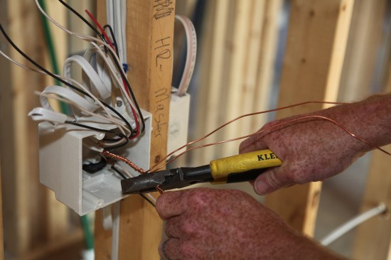
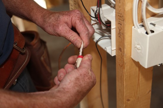
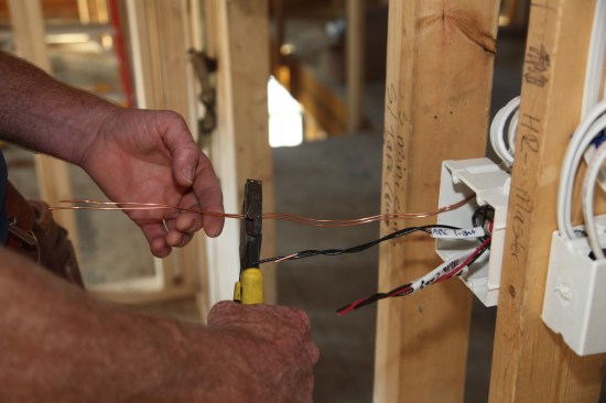
The author starts by twisting the two ground conductors together…
The author starts by twisting the two ground conductors together by hand.
Next the author uses pliers to tighten the twist.
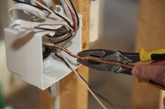
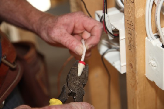
Because just a single ground conductor is needed, the author cut…
Because just a single ground conductor is needed, the author cuts off one of the connectors at the twist.
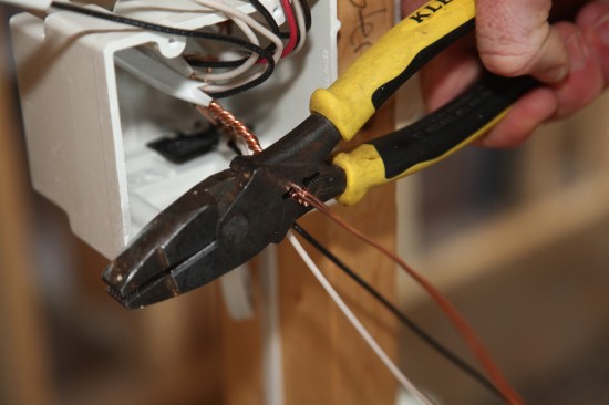
The proper size copper crimp sleeve slides onto the twist and pl…
The proper size copper crimp sleeve slides onto the twist and pliers crimp the sleeve.
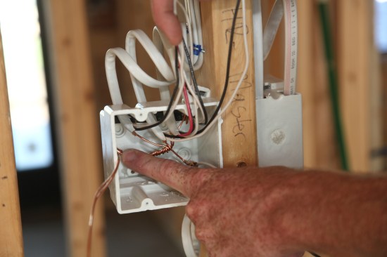
After pushing the twisted grounds to the back of the box, the co…
After pushing the twisted grounds to the back of the box, the conductors are all cut to a length of about 8 inches.
Finally the author rolls and folds the bundle of conductors and …
Finally the author rolls and folds the bundle of conductors and pushes them as far into the box as possible.
1
of 26
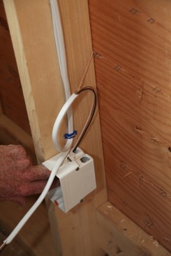
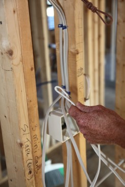
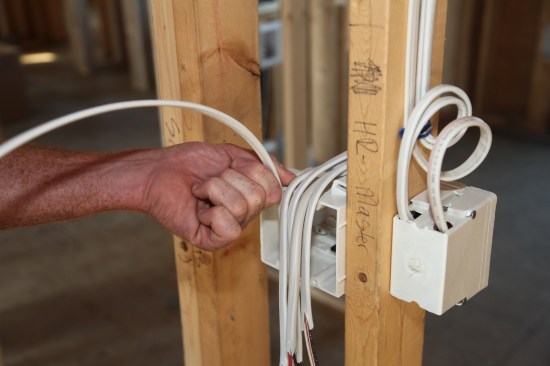
When running cable initially, the crew always bends the end of t…
When running cable initially, the crew always bends the end of the cable that will be supplying power to the switch box.
Roe Osborn
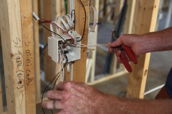
As cables are run to the box for the various lighting circuits, …
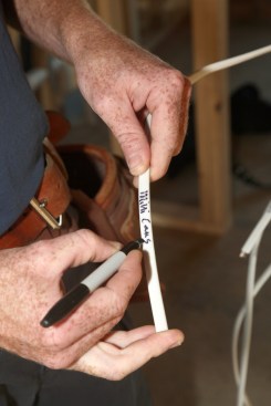
As cables are run to the box for the various lighting circuits, the outer jacket of each cable is labeled as to what the cable will control.
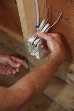
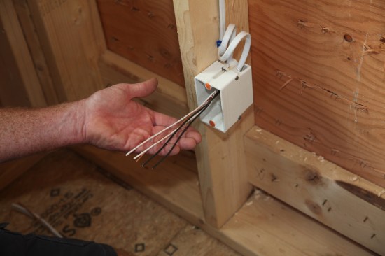
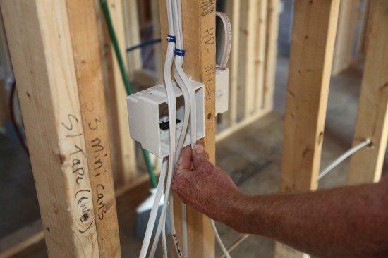
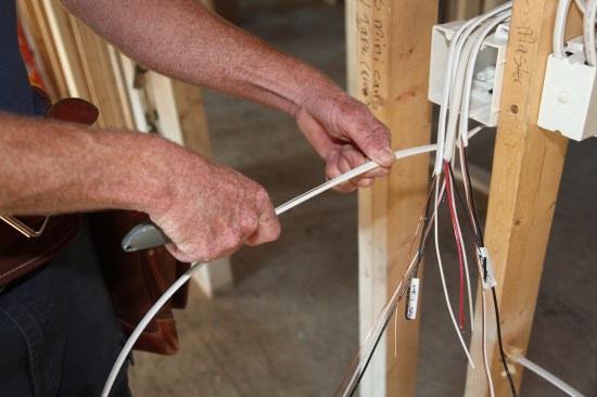
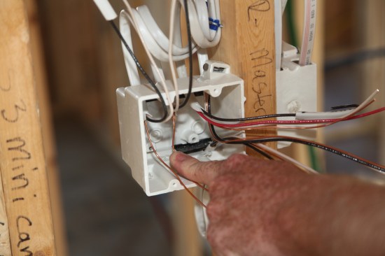
This switch box has five cables for two switches. After sorting …
This switch box has five cables for two switches. After sorting them out and grouping the cables together, the author gauges the first one for slitting the outer jacket using a finger and thumb.
After stripping a cable the author saves the jacket label and re…
After stripping a cable the author saves the jacket label and replaces it on the conductor from that cable.
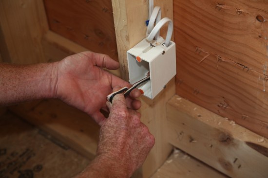
Cables fed from below the box are treated in the same manner. He…
Cables fed from below the box are treated in the same manner. Here the author gauges where to begin stripping the outer jacket.
The author slits the outer jacket from the lower cable. Notice t…
The author slits the outer jacket from the lower cable. Notice the progressively longer jacket length on the upper cables that have already been slit. The longer jacket lengths are needed to reach the farthest knockouts on the box.
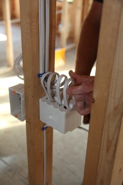
The author feeds the cables into the switch box leaving a loop i…
The author feeds the cables into the switch box leaving a loop in each one. Again the loop provides extra cable in the event that one of the conductors is damaged during the drywall installation.
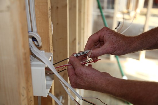
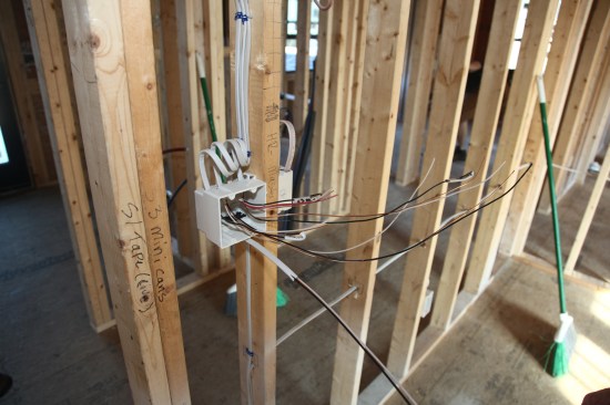
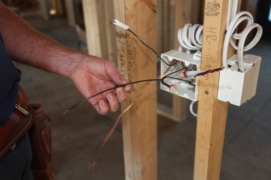
As the cables are fed into the box, they may look like an unorga…
As the cables are fed into the box, they may look like an unorganized mass of wire. But with the labels and the wire colors, sorting them out is easy.
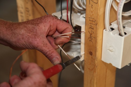
After roughly sorting the conductors for each of the switches, t…
After roughly sorting the conductors for each of the switches, the author pushes the grounds for one switch into the back corner to give them plenty of slack for bundling.
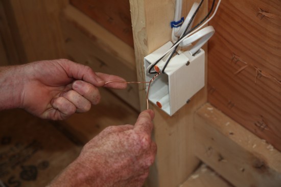
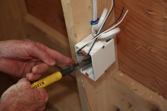
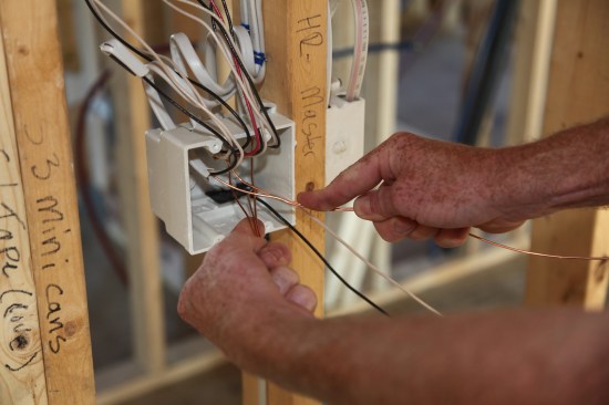
With two ground conductors in one hand and three in the other, t…
With two ground conductors in one hand and three in the other, the author begins to twist them together.
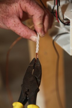
The author makes a half dozen twists by hand marrying together t…
The author makes a half dozen twists by hand marrying together the ground conductors from all five cables.
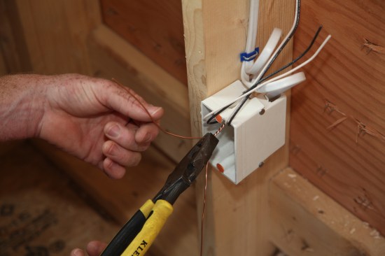
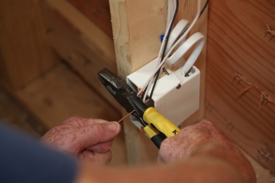
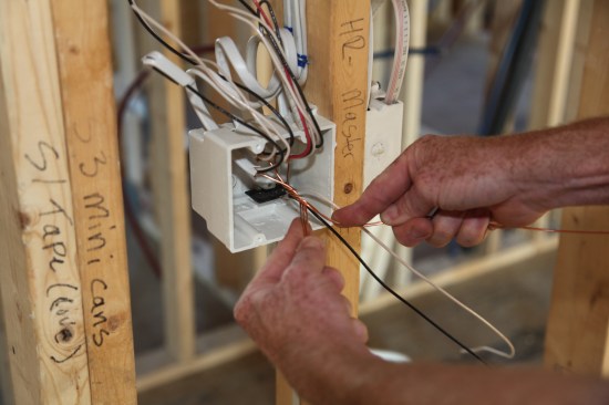
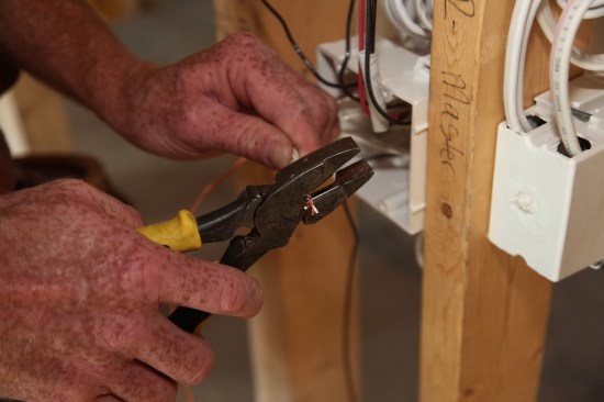
As before, pliers finish the twist tightening the bundle togethe…
As before, pliers finish the twist tightening the bundle together.
The author cuts all of the ground conductors but two–one for ea…
The author cuts all of the ground conductors but two–one for each switch.
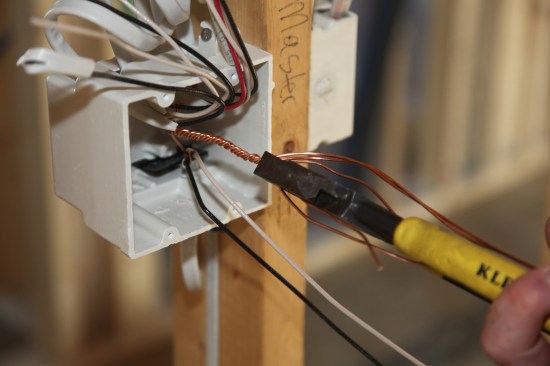
The proper size copper sleeve slips over the end of the ground c…
The proper size copper sleeve slips over the end of the ground conductor bundle.
A special crimping jaw on the pliers collapses and tightens the …
A special crimping jaw on the pliers collapses and tightens the sleeve to secure the grounds together.
After joining all the grounds together, the bundle is pushed aga…
After joining all the grounds together, the bundle is pushed against the back of the box.
After taking care of the grounds the author groups the neutral (…
After taking care of the grounds the author groups the neutral (white) conductors together for each switch. Each group will be bundled, joined together and capped.
After cutting the neutrals in each bundle to a length of 6 to 8 …
After cutting the neutrals in each bundle to a length of 6 to 8 inches, about an inch of insulation is stripped from the ends of the conductors.
Pliers twist the bundle of neutrals, joining the bare ends as we…
Pliers twist the bundle of neutrals, joining the bare ends as well as twisting a short length of the insulated sections together.
After twisting the conductors together snip the end of the bundl…
After twisting the conductors together snip the end of the bundle leaving about 1/2 inch of the twisted bare wire.
Twist the appropriate size wire nut onto the bundle tightening i…
Twist the appropriate size wire nut onto the bundle tightening it by hand as much as possible.
Use pliers to make a final twist of the wire nut, but take care …
Use pliers to make a final twist of the wire nut, but take care not to over-tighten the nut. After attaching the wire nuts push the neutral bundles into the back of the box.
A pigtail twisted with the supply conductors will feed one of th…
A pigtail twisted with the supply conductors will feed one of the switches. A short length of black conductor is twisted and wire nutted to the other two.
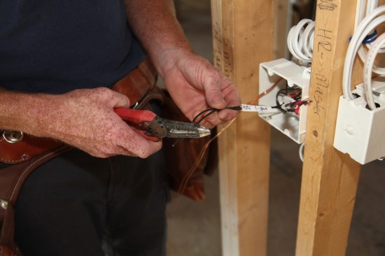
Stripping back the insulation on the
supply conductor identifies…
Stripping back the insulation on the
supply conductor identifies it for the crew that will be installing the switches later.
The final step is cutting off excess cable before rolling, foldi…
The final step is cutting off excess cable before rolling, folding and pushing each group of conductors into the box as far as possible.
Roe Osborn
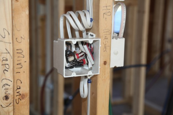
The finished box with all the conductors and bundles pushed as f…
The finished box with all the conductors and bundles pushed as far into the box as possible. Labels still attached to the conductors will let the crew member wire the switches quickly and efficiently.
An Organized and Consistent Approach
Earning a living by wiring houses, as with every job done by a professional contractor, requires doing the job as efficiently and safely as possible. The rough-in methods that I describe in this article have been learned and honed over decades of experience.
One prerequisite for a successful rough-in is keeping all the work neat, organized, and consistent. Most of the homes that we wire are custom-built for clients who expect meticulous work—regardless of whether the work is visible. That level of neatness reflects on the general contractor as well as on my company as the electrical contractor.
More importantly, my organized approach to roughing in makes it easy to trace or follow any circuit. When we finish roughing in a house, I’m confident that any member of our crew can ascertain at a glance what any circuit is meant to supply or control, as well as the path that the wires followed to get there. With dozens of circuits and many thousands of feet of wire in each of the homes we work on, keeping everything organized to an almost obsessive level means that in the end everything will work as it should without a lot of time-consuming troubleshooting.
Consistency in our work as a group means that any crew member following another to wire a switch or receptacle will always know exactly what every conductor in a box is meant for. This consistent approach lets the crew work at the most efficient speed to complete the project.
Gentle Wiring
Wiring a house—especially at rough-in—means pulling, stapling, twisting, and cutting the wires. In spite of that, the task of the electrician is to do all of those things in a way that creates minimal stress on the conductors—the actual metal that will be carrying the electricity. So I try to convey the mindset of “gentle wiring” to my crew.
The conductors in the cable that we use for most domestic wiring are made of copper, which is soft and malleable. While the flexibility of the material lets us easily fish the cable just about any place we want it, the soft, metal conductors are also subject to metal fatigue from continuous stress, such as sharp or repeated bends. Metal fatigue can result in scored or broken conductors, which in turn can cause short circuits, heat buildup, and in the worst cases, fire. Installing a safe electrical system is a huge responsibility that guides our work at rough-in and at every stage of wiring a house.
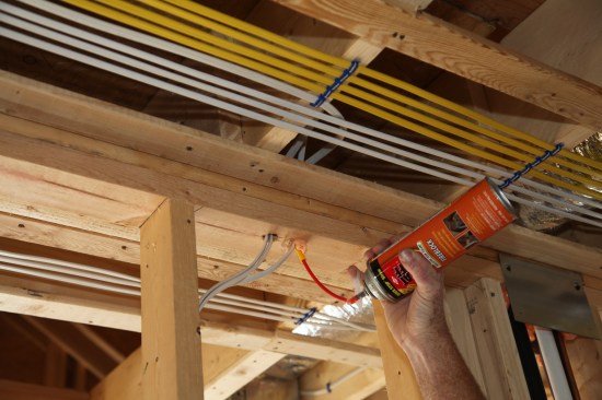
To finish the rough-in work, a crew member fills every penetration between floors with fire-resistant expanding foam to insulate against air movement and to help impede the potential spread of fire in the stud bays.
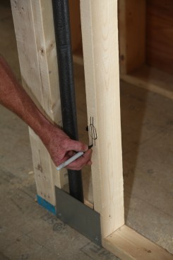
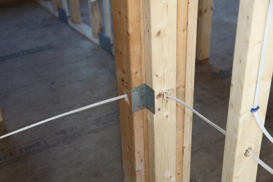
If the cable is within 1 1/4 inches of the stud surface, metal plates are required to prevent damage from errant drywall screws. Here, the angled hole to route
a cable a round a corner is too near the surface, so metal plates protect the cable on both sides of the corner.