
In a previous article, “Tracing Air Leaks With a Blower Door” (Nov/20), we discussed locating “areas of opportunity” for air-sealing—a last chance to easily tighten up the air barrier in a new home prior to drywalling and installing the exterior cladding. We advocated that making the effort to track these down can often add up to hundreds of cfm worth of air leakage reduction as well as help avoid building-durability callbacks down the road.
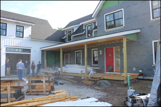
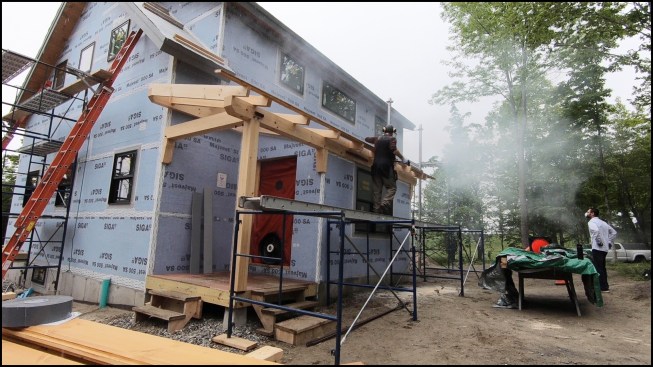
Air-sealing homes has much improved over the past 15 to 20 years. Here, the authors test a well-built Vermont home with a complex roof for air leaks using theatrical fog. The home’s multiple dormers proved to be well sealed by the builder’s conscientious crew (dormers are notoriously leaky spots).
Along with blower-door testing of new homes, we also conduct home performance assessments and energy audits on existing homes. This is when we often encounter the “usual suspects” with regard to air leaks, including poorly air-sealed can lights, bath fans, and top plates of partition walls in attics. In this article, we’re going to focus on air-sealing the framing—specifically as it relates to complex roofing, ganged framing, and “marriage” walls (walls between an addition and the main structure).
Problems related to poor air-sealing or unintentionally missed air barriers may take years to manifest, sometimes with harmful consequences to a home’s structural integrity and, in worst-case-scenarios, to the health of its occupants. In existing construction, because these locations are hidden behind drywall or buried underneath insulation, air-sealing errors can be difficult to find and expensive to fix. (For more on common air leakage pathways at critical building envelope intersections and air leaks related to mechanical, electrical, and plumbing penetrations, see “Practical Air-Sealing” by Steve Easley, Aug/2018).
This modern take on a Cape has shed dormers front and back.
The home’s thermal shell (2-inch EPS with taped seams sandwiched between the sheathing and 2×6 studs) was airtight, though some small leaks were discovered at the shed dormer framing and sealed before the wall assembly was completed.
COMPLICATED ROOFS
If we were to adhere to the principle “form follows function,” the ideal roof would be a simple gable over an unheated attic (much like the roof of a house a child would draw). On this type of roof, it’s not difficult to install an effective air barrier that is aligned with the thermal control layer, or insulation. But more often than not, roofs are complicated, with multiple valleys, dormers, and intersecting planes—more “form over function.” It’s not uncommon for homes to have conditioned space tucked under steep-sloped roofs—cathedral ceiling areas and the second-story knee walls on Cape-style homes are typical examples. When roofs are complex, they can be difficult to air-seal and insulate, difficult to ventilate, and—in a cold climate—prone to ice damming.
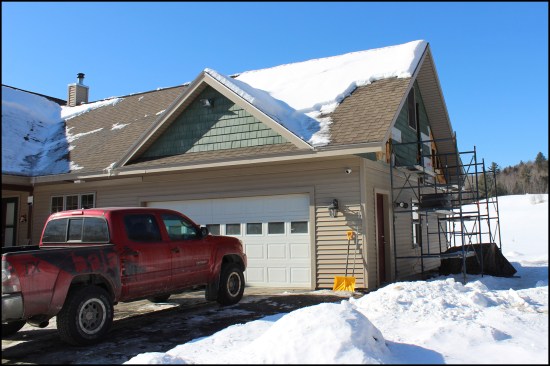
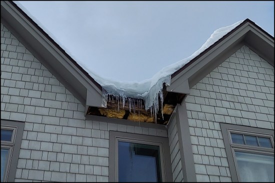
This circa-2006 L-shaped Cape with a bonus room above the garage had a history of ice damming, not only in the valley but also around the entire perimeter of the garage roof.
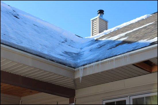
Heat loss from an exposed flue located in the transitional framing area where the roofs intersect (outside the existing thermal envelope) contributed to the ice damming, along with air leaks from the heated garage below the bonus room.
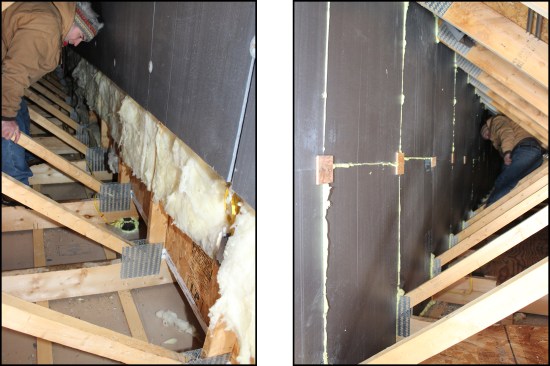
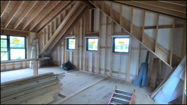
Working around the attic trusses, batt insulation was removed above the strapped ceiling drywall in order to air-seal ceiling penetrations, while the bonus room knee walls were air-sealed from the back with XPS foam (left, right). Cellulose insulation will later be blown in under the bonus-room floor and between the trusses.
Framing. When it comes to design, clients are often reticent to give up their ideas in favor of a simple, well-insulated and ventilated roof. For example, their new home or addition may have a roof detail that requires built-up quintuple 2×12 valley rafters to achieve its “form.” While this valley roof framing scenario may be structurally sound, it doesn’t “function,” because the built-up wood members can shrink, leading to unwanted air leakage pathways—small gaps between the framing members that are still large enough to allow airflow through the assembly. Under the right conditions, these small air leaks have the potential to transport warm interior air to the underside of the roof deck, where moisture can condense. This moisture, along with vapor diffusion through building materials, will rot the sheathing.
Without proper ventilation, warm interior moisture that has found its way into the thermal envelope has no way to escape or dry out. And, just because a design may have created a contiguous, aesthetically pleasing surface on the home’s interior, it doesn’t mean that surface is airtight. Air infiltration can occur at penetrations, framed intersections, and massed framing locations, such as at wall and ceiling corners behind the drywall. Wherever we need large built-up framing to support heavy structural loads, the design of that structure must accommodate shrinkage to avoid air leaks. It also must be thermally broken to prevent significant conductive losses and cold spots where moist air will condense and grow mold. It’s commonplace to think only about the structure and to ignore the flow of air, moisture, and heat.
Bypassing the drywall air barrier. Finished and painted drywall can be an effective air barrier, but on flat ceilings, warm moist air bypasses the drywall via air-sealing misses at penetrations like bath fans and can lights, leaky attic hatches, and chimney chases. With cathedral ceilings, warm, moist air gets into rafter bays typically through light fixtures, fire alarms, and other penetrations. Often, we find cathedral ceilings that are clad with shiplap or tongue-and-groove paneling without any air barrier. Areas where the ceiling material joins other building surfaces serve as potential leakage pathways, as well. Diffusion through building materials also occurs, usually a small amount, but enough to add moisture to the roof assembly.
The spray foam “solution.” One way builders often try to create effective thermal and air control layers on a complex roof is with closed-cell spray foam in the rafter bays. But we’ve found in our area of Vermont (climate zones 5 and 6, with 60-pound snow loads) that this solution doesn’t work well. Even when the foam is properly mixed and applied, the framing members shrink, especially in attics where the installers are not spraying over the edges of the rafters or encapsulating the truss chords. In these cases, gaps between the spray foam and the wood framing can leak air. The problem isn’t with the foam itself, and applying a thicker layer of foam (filling deeper cavities with more) won’t alleviate the problem in colder climate zones. And once warm indoor air meets up with the layers of roof sheathing and nonpermeable roofing underlayment, it becomes trapped in a “vapor sandwich.” In our opinion, the solution is to install a roof ventilation channel in each rafter bay before spraying the bays with foam. When properly connected to soffit and ridge vents, this ventilation channel will allow any assembly moisture that escapes through small cracks in the framing to safely vent outside.
Because of discovered issues—including ice damming, black mold, and rot—that we’ve seen with foam-insulated hot roofs in our climate, we’ve become firm believers in proper roof ventilation.
Spray foam was applied to the underside of the decking with no ventilation channel on this northern Vermont home built in 2008, to create a hot roof.
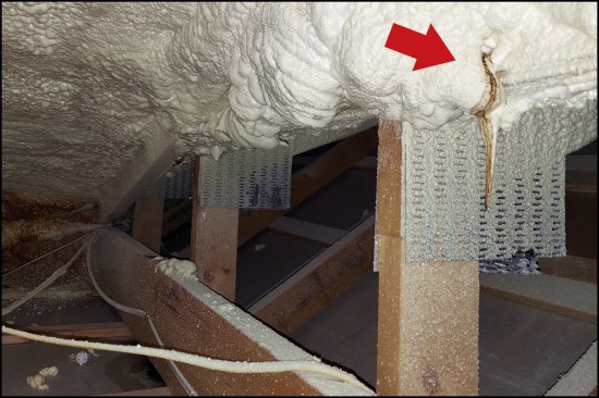
Here, “tea-staining” leaking from above indicates where moisture transported by warm air flowing through cracks between the foam and the framing has condensed on the roof sheathing.
AIR-SEALING WALL FRAMING
Problems with insufficient air-sealing occur not only with roof framing, but also with wall framing, especially when multiple members are sistered together. Built-up jack studs to king studs, headers, and corners are all common culprits. When assessing existing construction with a thermal camera, we often find corners where the framing has separated and allowed a stream of cold air to infiltrate the space. That’s why we emphasize using a proper sealant to air-seal built-up framing. Pay close attention to inside and outside corners, ganged jack studs and king studs, multiple-ply headers, and double top plates in new construction. These measures are mostly done for durability reasons (to prevent streams of air that can condense on cold surfaces and begin to rot the structure).
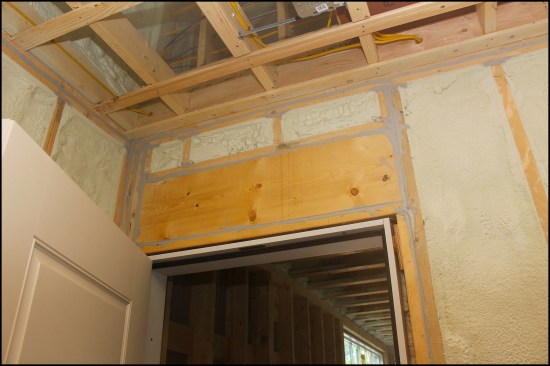
Above, the door header, jack, and king framing of an attached, unheated garage has been air-sealed with a quality sealant. Seemingly small, unsealed gaps between framing members become significant pathways when depressurization happens in the home via appliances such as dryers and range hoods.
Knee walls. On Cape-style homes and in bonus rooms over garages, fixing poor insulation and air-sealing in tight spaces behind second-floor knee walls can be a challenge. Often we find poorly installed fiberglass batts on top of ceiling drywall with a poorly defined air barrier and air gaps everywhere, even on relatively recently built homes. In a cold climate, warm, moist air passing through these gaps inevitably finds its way into the attic.
Marriage walls. When an addition has been built onto an existing house, we often see problems where the framing for the addition is fastened to the existing sidewall. The problem isn’t with the framing cavity, which typically is well-insulated; it’s with the joint itself, which seems insignificant until air flowing through that joint and up into the attic space of the existing house starts to create moisture problems. Typically, the attic is above the home’s thermal boundary, and any indoor air that leaks into this space is likely to condense on any cool surfaces, creating big problems.
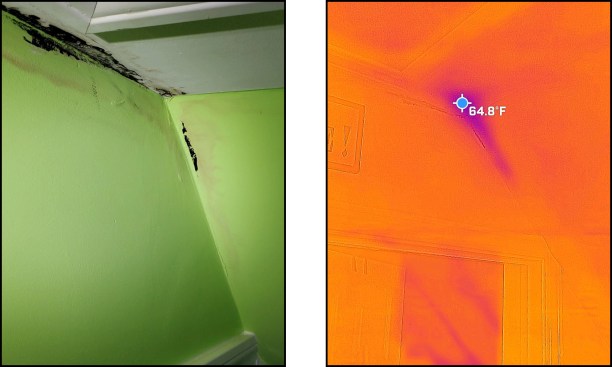
Mold appeared on the ceiling of a marriage wall between the addition (circa 2012, insulated with spray foam) and the main home (left). Infrared images (right) …
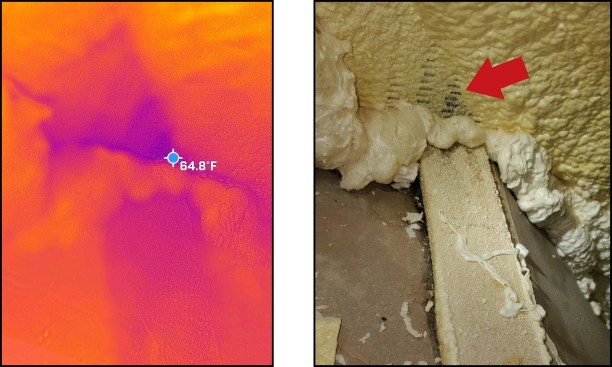
… and (left) zeroed in on the foaming “miss” of a exposed truss plate abutting the unheated attic space of the old house (right).
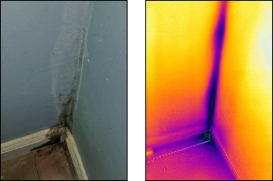
Lower on the same marriage wall of this otherwise fairly tight house, a gap in the framing occurred because of shrinkage of the framing member. The airflow led to condensation and mold (left, right). Initially, closed-cell spray foam was thought to solve most air-sealing problems, but the authors believe that sealants (such as caulking, membranes, and air-sealing tapes) and a better understanding of ventilation are needed to avoid condensation problems in cold climates.
Appliances. Clothes dryers, bath fans, and range hoods can exhaust a considerable amount of air from a house. For example, a typical clothes dryer runs at 300 cfm, while a bath fan runs as high as 130 cfm. If there’s a fireplace, that can draw 500 cfm or more if there isn’t a makeup air supply. The exhaust fan over a kitchen range can run at 600 to 900 cfm or even more. All these “exfiltration loads” can put the house under negative pressure.
When a home is depressurized, air will be pulled through any unsealed gaps or seams between adjoining framing members, intensifying these leakage pathways and increasing the potential for problems. It’s critically important to get the air-sealing details correct, even on the most granular level.
Photos by Jim Bradley, Chris West, Sebastiaan West, and Tim Healey