Carpenters don’t have to know the calculations for sizing each component or analyzing the stress values on components and connections, but it’s helpful to know how structural systems interact to keep a building upright and also to know how it might fall down. The latter is especially critical when it comes to demolition; you don’t want to just start cutting joists or knocking out walls. Instead, you want to be able to “read” a structure to know what is essential to its support, so you can safely remove some parts while temporarily supporting others as you take the building apart.
It’s also useful to know why you need to follow nailing schedules and why it’s important to select the right size lumber and fasteners when assembling structural components. Lumber sizes and the diameter and length of nails and structural screws are not arbitrary choices; they are determined by the structural demands of the building.
Related Articles
In This Series:
Structural Design Basics
Beam Stress and Strains: A Lesson in Statics
Practical Engineering articles:
Calculating Loads on Beams and Headers
Sizing Engineered Beams
This article begins a series of articles that will introduce new carpenters to the principles of structural design with an eye toward better understanding how to assemble and dismantle structures. This first article introduces some terms used to describe forces and the general components that are part of the framing to resist those forces. In other articles, we will elaborate on different parts of the frame, as well as tackle principles that relate to a building’s other major structural system, the foundation.
Be patient as you wade through this material. The forces acting on buildings are a complex of energies acting in different directions at once. To make them rational and measurable, engineers methodically break them down into discrete forces resisted by distinct components and specific properties of materials. Taken by themselves, they will seem abstract, but as you gain an understanding of these terms, you will gradually be able to put them together to analyze how a structure works, and some of the ways it can fail.
Loads On Buildings
Let’s look first at some of the terms used to describe the loads on a building.
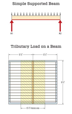
A simple supported beam (top) is one supported at each end. Half of the uniform load spread across the beam’s length equals the “reaction force” at each end. Between the supports, the beam can bend and flex. To begin to measure the load on the beam, we need to look at the “tributary load”—the portion of the loads on other framing members that feed into the beam. In this case (plan view of a floor frame above), a floor beam supports half the load on the joists on both sides. The other half of the load on the joists is supported by the foundation walls on each side
Dead and live loads. As the name implies, dead loads are unmoving, or static, and primarily include only the weight of the materials the building is made from. Live loads are dynamic—they come and go, and when present, may impose greater and lesser force on the building over time. Live loads include snow loads, which are mostly added weight pushing down from the roof. Live loads also include people, furniture, appliances, equipment, and such—changeable weights and vibrations that come and go and move around. Live loads may also be of variable strength: Wind, which moves at different speeds and imposes both positive and negative pressures that push and pull on a building, is one example. These loads can be extreme (see “Wind-Resilient Buildings”), as are seismic loads from earthquakes—another example of extreme live loads that vary greatly in magnitude and are a greater risk for buildings in some locations than in others.
Positions of loads. To begin to measure the strength of a material and evaluate its ability to support a given live or dead load, engineers have to distinguish exactly how each load is distributed across the building.
A “uniform load” defines a load evenly spread across a structural member. In reality, loads are never evenly distributed; on a floor, for example, they are concentrated where furnishings and people are, and they can move around. But to size the member, structural designers will assign a uniform load, typically measured in pounds per square foot. This load is based on assumptions to accommodate the shifting nature of real live loads, and a safety factor is typically added to the load.
In contrast to a uniform load, a “point load” is a load concentrated on a small area. An example would be a column supporting one end of a floor beam. In this case, a portion of the load on the beam (the uniform loads on joists that tie into a floor beam on each side) that is supported by the column is concentrated into a small area the size of the end of the column. To size the footing that supports this column and to specify the right concrete for it, we need to know what this point load is.
A “tributary load” describes the portion of a load that is supported by a member, such as a floor beam (see illustration, above). The load is defined as an area of the building from which forces flow (think water) to a supporting member.
Stresses On Buildings
Loads impart forces on building components, so we need to look next at the terms used to describe different types of forces that a building must resist to stay upright.
Compression pushes building components together. When under a compression force, the molecules in a piece of framing lumber are squeezed together; the force acts to shorten the material. If the compression is too strong for the material to resist, it may be crushed or the member may buckle. Some of the more common compression loads on a building are gravity loads: Heavier materials impose more downward compression force than lighter materials.
Tension is the opposite of compression; tension pulls materials apart, acting to elongate a material. Building materials react in different ways to excess tension: Concrete, which is very strong in compression, but exceedingly weak in tension will crack or crumble under a tension load. Steel, which is strong in tension, will elongate under an extreme tension. Wood’s ability to resist tension is decent if stretched parallel to the grain but much lower if stretched perpendicular to the grain (when it tends to split).
Shear is a stress that wants to make adjacent materials move past each other. The illustration at left shows some of the ways shear acts on building components. When you see the phrase “lateral load,” this refers to shear forces acting in a direction parallel with the ground surface.
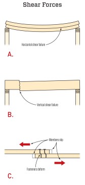
Shear stresses can cause adjacent materials to want to slide or slip past one another. In a wood member, horizontal shear (A) acts parallel to the wood grain, while vertical shear (B) acts across the grain. Shear is also a big factor in the design of joints and the selection of fasteners and structural hardware (C).
Beams And Columns
Most framing components in a house are either beams or columns. Most horizontal members are beams and most vertical members are columns.
“Girder” can be a synonym for “beam,” in general terms, but in practical terms, girder often refers specifically to a beam that supports multiple joists or rafters. Every joist acting on its own is a small beam, and every rafter a sloped beam. The headers over door or window openings are beams that support the loads coming down the studs or cripples in walls that bear on the header. Sills are beams that are uniformly loaded by the bottom plates of the walls and continuously supported by the foundation. Trusses are complex components that will be examined in detail in a later article, but as a whole, each truss, whether in a floor or a roof system, functions as a beam. Even every wall, taken as a whole, can be looked at as a beam, subject to the same complex of bending forces, which include compression, tension, and shear.
“Post” is a often considered a synonym for “column,” but in precise terms, columns are vertical members that support loads from above, in addition to lateral loads. Posts do not support overhead loads. A guardrail post, for example, is an important structural member on a deck that is supporting lateral loads but is not supporting overhead loads. In a wall, every stud, considered on its own, acts like a column, and king and jack studs work together as a column to support each end of a header. The supports at the ends of girders and structural ridge beams are columns.
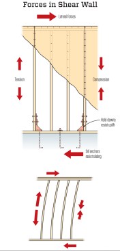
When strong wind or an earthquake exerts a force, the load is delivered to the top of the shear wall, along the plates. As the shear wall resists the load, one edge is put in tension, the other in compression. Anchors at the corners keep the wall from tumbling sideways.
Shear Walls And Diaphragms
More-complex assemblies that support buildings are shear walls and diaphragms. All wall sheathing helps to resist shear. When a lateral force is applied to a wall, it’s often called a racking force, because it wants to “rack” the wall, tipping the studs out of square. A diagonal brace or piece of OSB nailed to the studs and wall plates is enough to resist the shear imposed by normal wind loads. But for extreme loads, a true shear wall is needed. Shear walls are specific assemblies that include tight nailing on all edges of the plywood (and sometimes blocking, so all edges can be nailed off tightly) and hardware to keep the corners of the shear wall anchored to the foundation to prevent it from tumbling.
Similarly, lateral forces can throw a framed floor system out of square, and floor sheathing ties it together to keep it square. But a true diaphragm is a way to resist extreme lateral forces from windstorms and earthquakes. Diaphragms not only require specifications for the size of the joists and specific nailing patterns for the sheathing (and may include sheathing on the bottom of joists as well), but may also include “force collectors”—added horizontal members in the floor that are heavily sized and anchored with hardware to the walls.
In later articles in this series, we will look closely at all these components, beginning with an examination of the complex of forces that cause beams to bend and columns to buckle, and what goes into sizing these members to limit these distortions.
Illustrations by Tim Healey