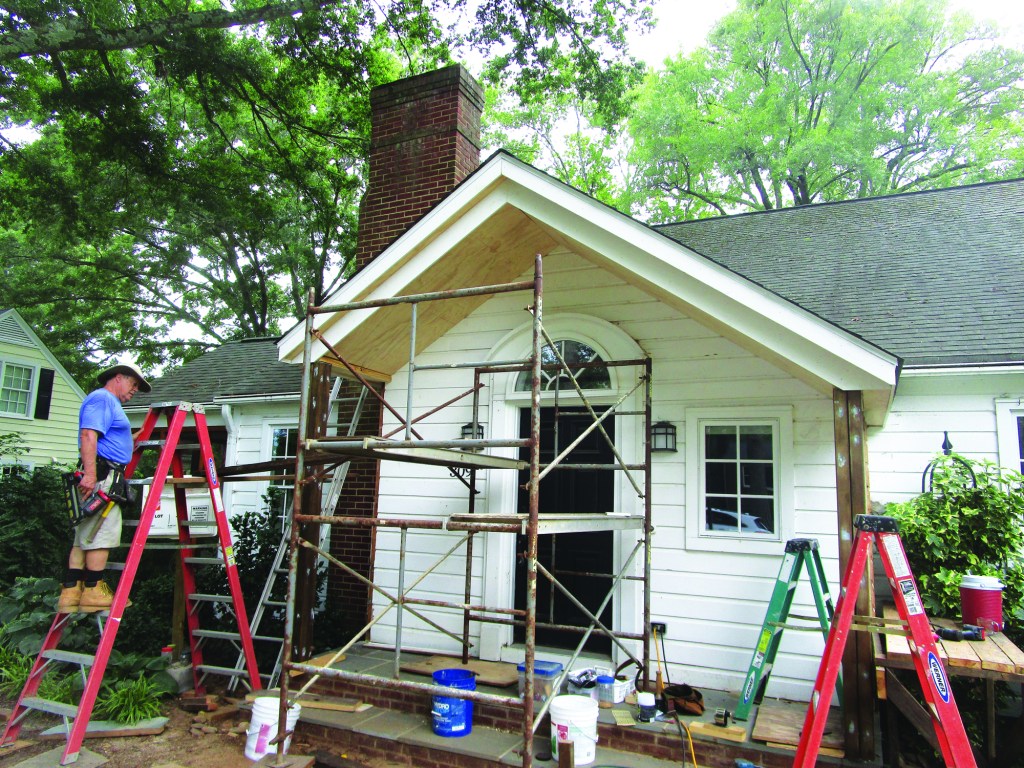
Like many houses built in the post-World War II building boom, this modest cape (built in 1951) originally had no roof over the front porch. The brick and concrete stoop served the most basic function of a porch, but anyone waiting at the front door was exposed to the weather until the door was opened. And because the area just above the concrete slab got soaking wet when it rained, the wood siding, trim, door, and mudsill had all been repaired for rot over the years. In addition to these practical shortcomings, the sad little stoop detracted from the appearance of the otherwise attractive and impeccably kept house and yard.
To create a more practical entry, the owners hired their niece, architect Sophie Jonson, to design a portico (a structure consisting of a roof supported by columns, which is often attached to a building as a porch). The design had to be approved by the Historic District Commission of the town of Hillsborough, N.C., and it had to conform to the rules and regulations of the town’s Building and Planning Division. The historic commission was easy to satisfy: The design fit the architecture of the house and specified traditional materials (brick, stone, and wood) that would have been used in 1951.
The building and planning division proved harder to please. The existing stoop was in violation of current setback limits but, because it had long been in place when the setbacks were enacted, it was grandfathered into legal acceptance. That meant that we weren’t allowed to tear down the stoop and build the new portico from scratch. Instead, we would have to improve the existing porch without encroaching further on the setback limits. We could add to the sides of the stoop but not to the front, and we were required to leave the existing stoop in place. To satisfy these requirements, Sophie designed the portico to more than double the 6-foot width of the stoop while maintaining the 40-inch depth.
John Carroll
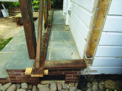
To expand the original front entry, the author removed its concrete slab deck.
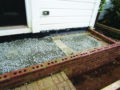
Then he laid up a pair of block walls faced with brick on either side of the masonry stoop.
Before pouring a new slab flush with the brickwork, he installed vinyl flashing to serve as a vapor barrier between the concrete and the mudsill and primed the cut edges of the siding and trim.
Extending the Brick Stoop
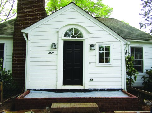
Because I was required to leave the existing stoop in place, I had to build two separate foundations, one on each side of it. After digging and pouring small rectangular concrete footings, I laid up two rectangular concrete block foundations and set rebar dowels in the cores with grout. I covered the visible sides with bricks that matched those on the house.
In keeping with the town’s requirements, I left the brick walls of the existing stoop in place and ran the new brick into it, then ran the top two and a half courses of new bricks over the top of the existing ones. Since evidence of the existing stoop was rapidly disappearing, I took numerous photos to document that I had indeed left it in place.
To tie everything together, I took off the concrete top of the existing stoop and poured a single slab that bridged the three separate foundations. The dowels I had inserted tied the slab to the block foundations. In case the three foundations settled unevenly, I reinforced the slab with a grid of 1⁄2-inch rebar to keep it from cracking.
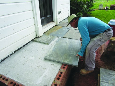
The author dry-fit the bluestone pavers, numbering them to keep track of their location.
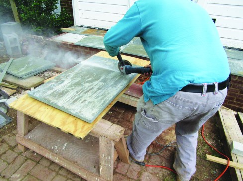
He trimmed them to size as needed with a diamond blade mounted in an angle grinder.
The slab rested on the blocks but ended inside the brickwork, which I used as a form to strike off the concrete. I had laid out the brickwork so that the tops of the two sides sloped a full inch downward away from the house. Doing this insured that the top of the slab would also slope about 1/4 inch per foot over its 40-inch width to shed any rainwater that might blow onto the deck.
Before mixing the mud for the straight-edged Pennsylvania bluestone pavers, I laid them all out over the entire slab, cutting them as needed with a 4 1/2-inch angle grinder equipped with a diamond blade. Along the outside perimeter, I overlapped the wall 1 inch; along the house, I tucked the stone under the siding and trim. To keep the joints uniform in size, I used a 1/2-inch plywood scrap as a gauge. After laying out all the stones, I numbered them and removed them from the slab.
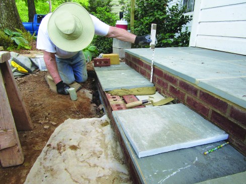
The pavers were set in a thick bed of type S mortar. After the mortar bed cured, he grouted the 1/2-inch-wide joints with the same type S mortar.
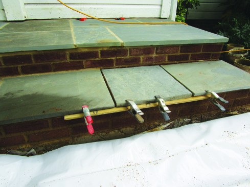
A strip of wood clamped to the pavers where they overhung the brickwork supported the grout while it cured.
Next, I set the stones in a bed of Type S masonry cement mortar mixed to a ratio of two and a half parts sand to one part masonry cement. The stones were natural cleft, meaning they were split and, thus, not uniform in thickness. To ensure that they were fully embedded in the mortar, I mixed the mortar fairly wet and spread it slightly high. I set each stone into position and tapped it down to its final resting place, making sure to keep the top surface in a straight plane that sloped down towards the outside edge.
Once the mortar bed had time to cure, I grouted the joints using the same Type S mortar mix. Around the perimeter, I used spring clamps to hold a strip of wood to the underside of the stone. This strip supported the mortar as I packed it into the joint in the 1-inch section that overhung the side.
After finishing the masonry part of the portico, I built a step that was 17 inches wide and extended the full 13 1/2-foot length of the masonry base (the step was exempted, surprisingly, from the setback restrictions). I poured a footing, and then built the step with bricks and stones to match the porch.
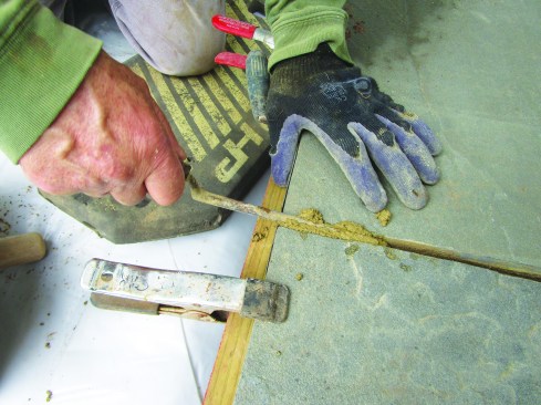
The author used a tuck pointer to pack the joints.
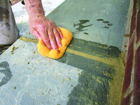
He cleaned up the joints afterward with a damp sponge.
Framing the Portico
When I first looked at the plan, there seemed to be no provision for keeping the ridge from dropping and the rafters from thrusting out at the bottom. When I voiced my concerns to the architect, she reassured me that she had consulted with a structural engineer and was confident in the design, explaining that the narrow width of the roof would mitigate most of my concerns. She agreed that the connection of each pair of rafters would need to be reinforced by securely fastened collar ties located just under the ridge. She also emphasized the importance of a strong connection between the new roof and the existing roof.
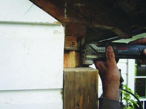
After removing the trim at the house corners and eaves, the author used a multitool and sharp chisel to cut pockets in the solid 4×6 corners for the beams that would support the new portico roof.
Because of the asymmetrical design of the 1951 home’s front entry, both the entry door and the ridge were off-center, with different wall heights on each side of the projection and different rafter lengths. Sixty-eight years later, I would have to extend the off-center ridge and install beams at different heights to match the existing structure. All had to be supported on temporary posts over a stone floor that sloped a bit more than 1⁄4 inch per foot. It was a head scratcher at times.
I began by laying out the positions of the triple 2×6 beams and the 2×8 ridge in plan view directly on the stone deck. Before installing the ridge, I double-ripped the top to match the 34-degree pitch of the roof so that the plywood sheathing could be tightly nailed to it. Then, when I extended the beams and the ridge out from the house, I used a straightedge and a level to position and brace them directly over the layout.
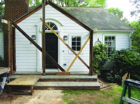
To accurately lay out and support the triple 2×6 beams and 2×8 ridge, he installed vertical posts and diagonal bracing fastened to a temporary plate on top of the new masonry stoop.
The plate was held in position with strategically positioned blocking.
With a stone deck to work off, bracing was challenging. Since I couldn’t nail a temporary plate to the stone pavers, I extended my plate across the full width of the porch and over the sides. On both ends, I placed a block of wood tight to the edge of the pavers, then screwed through the plate into the blocks to hold the ends of the plate in place. To secure the plate front-to-back, I cut blocks of wood that ran over to the wall of the house and fastened them to the plate and house with screws. With this plate in place, I was able to anchor the bottoms of braces that I used to plumb the three temporary posts that held the 2×8 ridge and beams precisely above the layout.
Installing the Roof
Before laying out the rafters, I measured the pitch of the existing roof using a level and a handy tool called a Pivot Square. To find the rafter length, I measured from the beams to the ridge, then used the Pivot Square set to 8-in-12 to lay out the plumb cut at the top of each rafter and the birdsmouth at the bottom. I doubled the first pair of rafters and fastened them to the rafters on the house with 6-inch TimberLok heavy-duty wood screws, placing about a dozen in each rafter. Hurricane ties connect the rafters to the beams.
I used 3/4-inch plywood to sheathe the roof to match the solid-sawn 1×6 sheathing on the house and to provide a stiff structural diaphragm in the new roof’s deck. At the seam between the old and new roof frames, I used an abundance of nails in both the plywood and the solid sawn sheathing on the house, tenaciously attaching the new frame to the old.
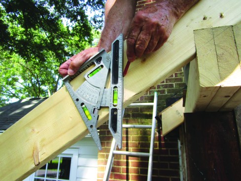
The author used a Pivot Square (chhanson.com) to accurately measure the slope of the existing roof, placing it against a level to find the 8-in-12 pitch.
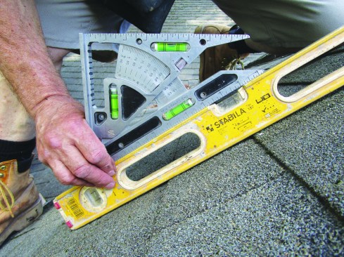
Then he set the tool to that pitch and used it to lay out the birdsmouths and plumb cuts on the rafters.
After fastening collar ties to the rafters and ridge with structural screws, I built the ceiling down 3 1/2 inches. This covered the flat section created by the collar ties and allowed the ceiling to run up to a point. It also created a second layer along the gable end, where I installed a pair of rake frieze boards under the last rafter and about 5 inches in from the rakes.
I cut the rafter tails in place and simply continued the eaves, which were about 5 inches wide, out from those on the house. To build the rakes, also 5 inches wide, I simply cut the plywood 5 inches outside of the last rafter, then clamped a 2×4 barge rafter in place under the plywood and drove screws through the plywood to attach the rafter. To provide a nailer for the plywood on the underside of the rake, I nailed 2x4s to the side of the last rafter.
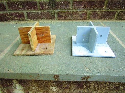
A local supplier fabricated the custom steel column brackets based on a plywood prototype supplied by the author.
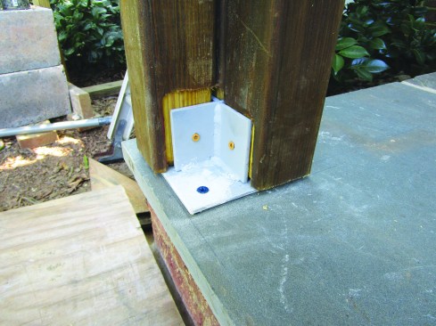
Each column consists of four 3×3 posts connected via the brackets to the masonry stoop …
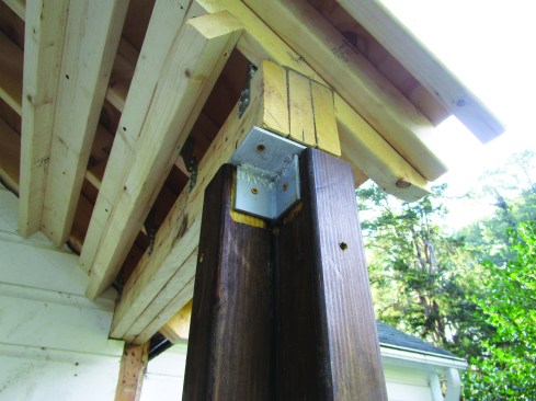
… and the beams.
Built-up Columns
Each of the two finish columns consists of four custom-milled 3×3 posts fastened at the top and bottom to custom-fabricated steel brackets. After bolting the brackets in place on the underside of the beams, I plumbed down to mark their positions on the stone deck, pre-drilled holes for 3-inch Tapcon concrete screws, then bolted the brackets to the stone deck.
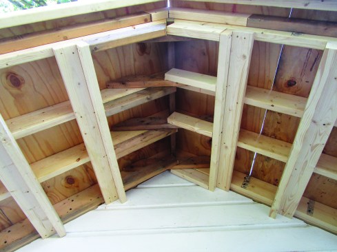
The author fastened collar ties to the rafters and ridge with structural screws.
He blocked out the roof framing with 2x4s to provide nailing for the plywood ceiling.
I milled the four 3x3s that make up each column out of 4×4 PT posts that I sanded smooth, rounded over the corners of, and stained. Each post also had to be routed to fit over the thickness of the steel brackets. I installed them one at a time, bolting through holes in the brackets to attach them securely at top and bottom and also driving deck screws through the sides to tie the wooden pieces together.
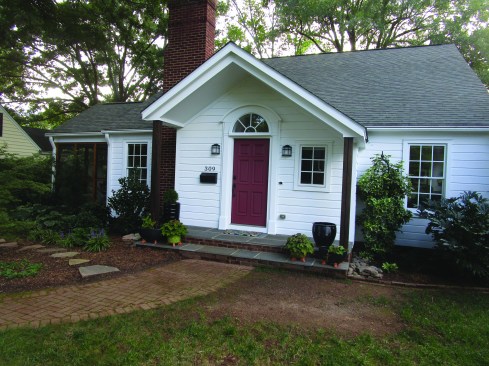
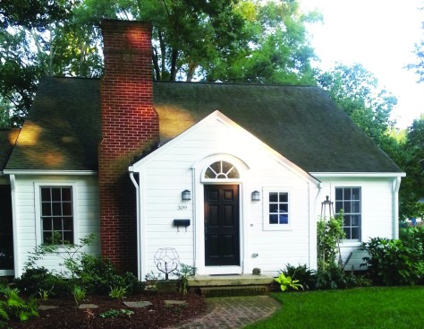
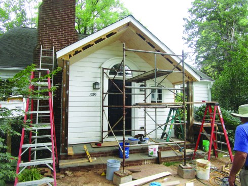
The completed portico was painted to match the house.
While construction took longer and was more expensive than my clients anticipated, they’re pleased with their home’s new portico. And because this part of North Carolina sometimes gets struck with hurricane-force winds, it’s nice to know that the strong, bolted connections between the deck, columns, and beams might just keep the roof from being blown away.
Photos by Matthew Carroll Navey