There is no accepted engineering practice for determining the magnitude of lateral loads in a given deck design. Different sizes and shapes of decks have different dynamics in loading, but the anchor detail made it into the code without that consideration. Consequently, the 1,500-pound restraint required at each of two anchors is empirical and essentially unfounded, as it doesn’t relate at all to the structure at hand.
The code requirement does set a bar that one could attempt to reach in other ways, many of which are feasible on existing homes. When you’re faced with the destructive nature of installing anchors inside a home, it’s worth considering an alternative to what the IRC offers.
Deck Harness
The International Code Council’s I-codes set a level of performance for buildings, but do not limit how that performance is achieved. ICC-ES is a nonprofit corporation that provides technical evaluations of building products, methods, and materials. ICC-ES does research to determine if alternatives are equivalent to the code, and shares the findings with the world. It also provides assurance to building code officials that alternatives meet the IRC’s performance requirements.
In June 2011, ICC-ES released a new Acceptance Criteria, AC430, for testing a cable-method alternative to the lateral load anchor published in the IRC. Acceptance Criteria are developed through a transparent process that solicits public comments. If you’re interested in this document, download it from icc-es.org/criteria/dsp.cfm?ac_code=AC430. Unfortunately, the method outlined isn’t necessarily any more realistic or feasible than the lateral load anchor. It still requires the floor sheathing to be nailed to the floor joists at a maximum of 6 inches on-center and the ceiling finish material to be removed, and it’s specifically limited to new construction. Currently, there are no products that have received an ES report as a deck harness.
Situations Not Covered by the IRC
The IRC doesn’t provide guidance about what to do for a lateral load anchor when floors aren’t framed of typical dimensional lumber or when the joists run parallel to the deck ledger (Figure 3). For these situations, you’ve got to do some objective thinking. What is the goal?
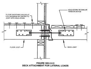
The anchor detail was put in the code to address the issue that a typical band joist is not designed to resist a lateral force. It has two primary jobs (without getting too technical about horizontal diaphragms). Nailed into the ends of the floor joists, a band joist resists rotation of the joists, a natural tendency when under load. This orientation puts a shear force on the nails extended through the band joist and into the end grain of the joists – exactly the force nails are best at resisting. The other function of a band joist is to resist compression; it transfers the loads of the wall above through itself and to the plate below. The band joist’s disconnection from the remainder of the floor system is a concern; bypass it or connect to other framing elements and you may be on the right track.
When joists run parallel to the band joist, the IRC detail is insufficient. If the goal is preventing the ledger from detaching from the house, a bit of blocking and longer bolts to connect the ledger to other parts of the floor system, like the first spanning joist in from the band joist, should be sufficient.
With engineered floor systems such as I-joists or floor trusses, there are bigger issues. These systems rely solely on the manufacturer and its engineers to determine what the product can do, so the first step is to find out who the manufacturer is. I-joists are usually labeled down the length of each piece of material. A quick search on the Web will likely yield manufacturer-supplied solutions that you can confidently install (Figures 4, 5).
These may look much like the lateral attachment detail in the IRC, but with the addition of web stiffeners between the flanges of the I-joists.
Floor trusses combine 2×4 framing lumber and steel gussets in standardized ways, and there are published load limitations for them. With that data, an engineer designs individual floors. One big difference between floor truss systems and other types of framing is that there’s no band joist. Rather, the trusses bear completely on the exterior plate or mudsill and are flush to the back of the sheathing. The trusses are then either blocked or provided a 2×4 on their upper outside edge to prevent rotation.
The Structural Building Component Association (sbcindustry.com) provides guidance for bolting ledgers to floor truss systems. Instead of being bolted to a band joist (because there is none), the ledger is bolted to the end 2×4 members of each truss and to blocking installed for this purpose (Figure 6). While I can’t speak specifically or with authority as to how well the end members of trusses are connected with regard to lateral loads, I can say that we are no longer dealing with a concentrated 1,500-pound load, as the lateral attachment requirement in the IRC posits. Rather, lateral resistance is generated uniformly by the bolted connection at each truss location. This spreads the load out over more members – a far better build in my opinion. Professionally, for the average deck, I would not be concerned that the loading would rip apart all the floor trusses in one catastrophic failure.
Lowest-Floor Decks
When a deck serves a floor resting directly on the foundation, my suggestion is to forget the home’s wood framing entirely. Drop the ledger and attach it to the foundation (this isn’t an option when the foundation has a masonry veneer); Simpson provides a detail for using its deck tension tie hardware (Figure 7). This approach will become more relevant going forward, as provisions in the 2012 IRC limit bolt locations in the ledger and the band joist, which will make it nearly impossible to step a deck down from the door, a popular design in snowy regions. The complicated bolting parameters in that code are a shocker and will be discussed in greater detail in a future issue of PDB.
Even simpler, when attaching the ledger to a concrete foundation, you can use published and tested loads for various concrete anchors for both vertical and lateral restraint (Figure 8). Achieving 3,000 pounds of tension resistance is easy through the use of these anchors, and resistance would be distributed more uniformly and along the entire length of the ledger, a far better construction than the two random and unspecified locations for the lateral load anchor method currently shown in the IRC. The values for tension published by manufacturers of epoxy, acrylic, and mechanical anchors are all at least 1,000 pounds for 1/2-inch-diameter fasteners. Any of these anchors, spaced at 12 or 16 inches on-center, will well handle the vertical and lateral loads of any common deck.
There are several other advantages to attaching the ledger to the concrete foundation. It’s likely below the exterior cladding, which therefore won’t have to be removed. The deck will also be below any cantilevered floor, which avoids all the issues of that connection (Figure 9). Not to mention that the lower the deck, the more privacy it affords the occupants. Lowering the deck increases the distance from the adjacent windows in the home to the deck floor, and could remove them from safety glazing requirements.
The only design contention to keep in mind is the additional steps from the exit door; a landing may be required if the deck is more than 15 1/2 inches below the threshold.