I started my career as a carpenter’s helper in 1981. Soon after, I became a general contractor and later opened a cabinet-making business, which I operated for 15 years before retiring last year. So when I built a cedar pergola a few years ago, I still owned a fully-equipped cabinet shop. This allowed me to cut all of the curved components on my CNC machine. These cuts could probably be made with a handheld bandsaw just as easily, but I didn’t own one of those at the time, and using the CNC machine on this project was fun for me and my helper.
Building a Kit
My plan was to prefabricate the parts in my shop, but first I coordinated the layout and installation of the column bases with the landscape contractor. I wanted to route the electrical conduit up through the posts, so the conduit from the house needed to exit finished grade as close to the posts as possible (unfortunately, we missed our target, and ended up needing a heavier base detail to cover the conduit as a result). Once the column bases were set and the elevations located with a laser level, I finalized my cut list– including post lengths–and got to work in my shop
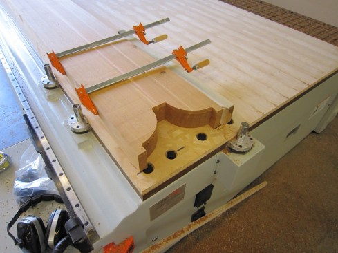
A CNC machine was used to cut out the parts, a pair at a time.
I started by programming my beam, rafter, and slat end details into the CNC. Since these were essentially mirror images of each other, I could cut two parts at a time, using clamps to hold them together. The parts rest on a spoils board, which has a series of holes drilled through it that allow direct suction to be applied to the assembly to hold it in place (plugging some of the holes with rubber grommets applies maximum holding power to the parts). It also allows the CNC bit to exit the cut without any tear-out.
To keep cuts as clean as possible, I programmed the CNC machine to make multiple passes and avoid taking more than about ½ inch on each pass. The long compression bit that I used has the depth of cut to do the lion’s share of the work and has 11/16 inch of upshear, while the remainder of the bit is downshear. However, my CNC machine is equipped with multiple bits, and I made my first pass with a shorter, ½-inch downshear bit. Otherwise, if I had used the longer bit exclusively, the first pass would have used the upshear portion of the bit and splintered the face of the workpiece. The beauty of a compression bit is that the final pass lifts the wood fibers on the bottom face and pushes down on the upper face, leaving no splintering on either face.
To keep the bit as cool as possible, I stopped the machine manually after each pass and blew the chips out of the kerf with compressed air (though I’m not sure whether that made a difference).
There is much more involved with using a CNC machine than I can go into here, and it wasn’t an essential tool. But the knee braces–which I cut one piece at a time–are an example of a perfect use of the machine. Not only did the machine’s accuracy make it possible to cut identical curves, but more important, it allowed me to precisely cut the 45-degree angles on the 4×8 material.
Hollow Columns
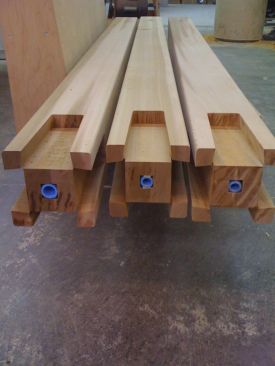
To create the channels for the electrical conduit in each column, I split them in half, dadoed half the channel in each half, and then glued the columns back together. Because the rough-cut 6×6 red cedar stock measured almost a full 6 inches, I had enough extra material to send each post through a planer to clean it up before making a pair of cuts on my table saw to split the posts. To help conceal the glue joints, I took care to orient them so that I was making the cuts in the faces with the most vertical grain. Afterward, I sent the post halves through the planer again to nibble off the saw marks and accurately dimension them.
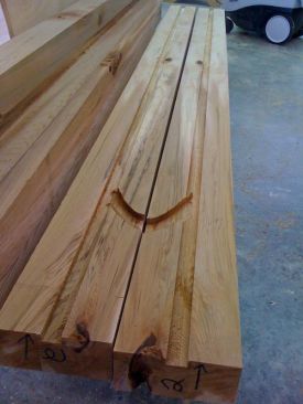
Electrical conduit passes up through the center of each red cedar post. To make channels for it, the author split the posts and and cut a dado on either half. Conduit exits the post above the base via a short channel, which was cut with a router.
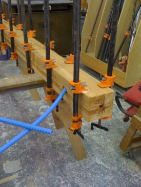
Then he glued the posts back together.
Dadoing on a table saw is straightforward, but I needed the conduit to exit the post just above the column bases in order to avoid conflict with the lag screws that secure the posts to their bases. For this, I marked the outlines with a quick plywood template and free-handed the cuts with a router.
I glued the posts back together with polyurethane glue and plenty of clamps. After sending them through a planer a final time to dress them down to the 5 ½ inches I needed for a proper fit in the column bases, the glue joints had virtually disappeared.
Tapered Dovetails
Instead of connecting the perimeter beams to the posts using metal hardware, I decided to fit them with tapered, dovetailed mortise-and-tenon joints. In addition to strength, this method gave me the pass-through look I was after and left the conduit chase intact through to the top of the post.
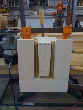
I sized the tenons to be as large as possible, to give the base of the joints ample bearing while offering that locking feature that the taper and the dovetail provide. Then to cut the mortises, I made a plywood pattern jig , which served as a guide for the router and as a work table for the router to ride on while cutting each mortise. A pair of legs screwed to the bottom of the jig helped center it over the posts and gave me a place to fasten my clamps.
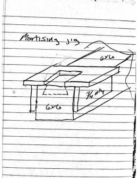
The author used a router guided by a plywood jig to cut the large mortises in the ends of the 6×6 posts.
To cut the tenons, the author screwed a plywood pattern to the ends of the perimeter beams. He also clamped a U-shaped jig to the beam to help support the base of the router while making the cuts.
To fine-tune the fit, I used the template to cut a sample mortise in a scrap post end, then experimented a little bit to come up with the right size for the counter template to cut the tenons on the ends of the beams. This is a simple plywood pattern that I could screw to the end of the beam, along with a U-shaped piece of plywood that I also clamped in place to support the router base (see photo). After a few tries, I felt I had two templates that worked well together.
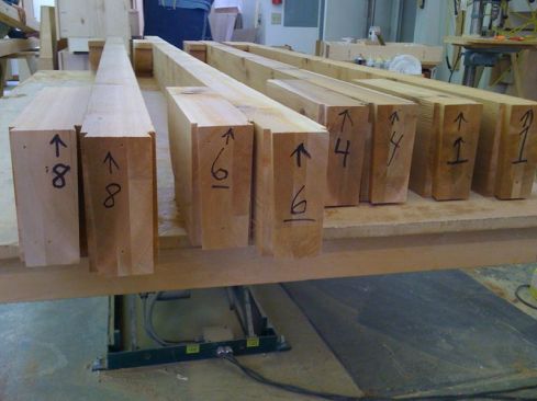
By now, I had cut all the posts to length and numbered them for position; I cut all the mortises in them first. Then I cut the tenons in the beams, which were also cut to final size and numbered. Because I was using a dovetail bit with a 1 ¼-inch depth of cut and because the tenons had to be cut in a single pass, a powerful 3 1/2-hp router was essential to the operation.
The completed columns, with mortises cut, are ready for installation.
Each perimeter beam has a matching decorative element that makes it appear that the beam is continuous through the column.
Each beam end had a specific mortise it needed to fit into, so as I cut each tenon I tested for accuracy, making any final adjustments as necessary with a file to remove a little bit of material here or there to get the right fit.
One of the last shop tasks was to make the counter bores and through-holes in the knee braces for their lag screws and washers, using my drill press. When sizing the lag screws, I had to take into account the electrical conduit running up the center of each post. I wanted the lags to be long enough to make a solid connection, but not so long that they would penetrate the electrical conduit.
Once the heavy work was completed, I cleaned up the parts with a heavy-duty random orbital sander. I marked the rafter locations on top of the beams, marked the slat locations on top of the rafters, and drilled pilot holes for the fasteners. Finally, I was ready to load everything up onto my trailer and bring it over to my house for installation, which after all the prep work in the shop was pretty straightforward.
Installation
I didn’t want to screw braces to the posts when positioning them, so I used clamps instead to hold them plumb until they were locked in place by the beams. I used a liberal amount of polyurethane glue at each post-to-beam connection, having planned for glue expansion by leaving about 1/16 inch of clearance between the end of the beams and the bottom of the mortise when cutting the joints. I was a little more conservative within the dovetail tenons, holding the glue at least 1/2 inch or so away from the shoulder, as I knew excess glue oozing from these joints would be nearly impossible to clean off later without leaving some evidence. Strap ties temporarily screwed across the tops of each assembly held everything together until the glue cured.
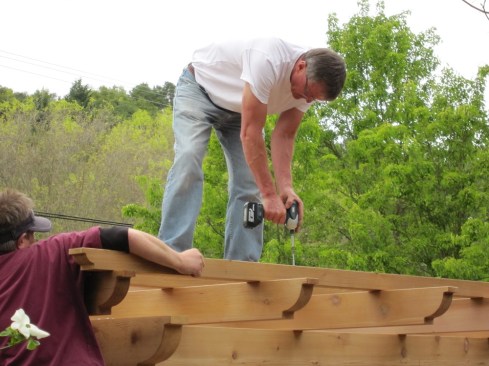
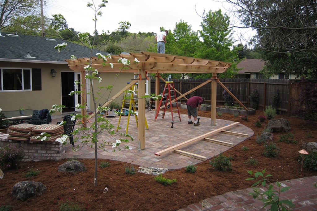
With all of the pergola parts prefabricated in the shop, actual installation went quickly.
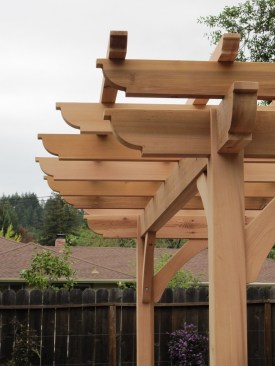
The end details on the pergola's beams, rafters, and slats are perfectly cut to match, thanks to the precision of the author's CNC machine.
I fastened the rafters to the beams with TimberLok structural wood screws, then screwed the 3×3 slats to the rafters with 6-inch HDG lag screws. Finally, before removing the braces, I installed the knee braces using 1/2-inch-diameter galvanized lag screws.
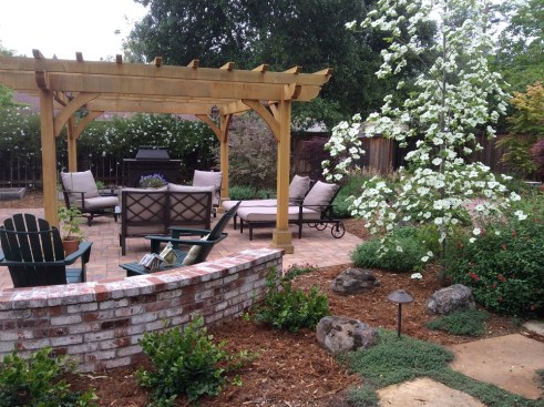
The finished pergola.
With the conduit pre-installed in each corner post, it was relatively easy to wire the pergola for lighting. We also added a custom-sized shade cover, which we bought from a company called Greenhouse Megastore. To ensure that the cover fit properly, I installed the grommets myself using a kit purchased at a local hardware store. For a total materials cost of about $3,000 in materials, including $2,500 for the western red cedar, we feel this is one of the best investments toward a comfortable retirement that we could have made.