The two-story block addition was “shoe-horned” in between abutting one- and two-story additions to the right and left. Masons apply brick veneer to the two-story block addition’s rear façade.
My company, R Corbo Improvements, specializes in remodeling inner-city row houses in Greater New York City and New Jersey area. For the last few years, our work has largely centered around rehabbing the lower two floors (of these four-story homes) into modern kitchen and living-room spaces. An important part of the renovations has been to introduce natural light into these long, narrow homes by opening up the entire back wall and installing large slider doors (see “Revitalizing an Urban Row House,” Mar/16).
Our remodeling work is usually confined to the building’s original footprint, but we’re occasionally asked to build an addition. For this story, I’m going to focus on the steps we took to build a 15-foot-wide-by-18-foot-long two-story block addition. Though we’ve built a few row-house additions in the past with other code-compliant noncombustible materials, such as structural steel studs with exterior gypsum board, we prefer to lay up block walls.
1
of 10
Remodeling in the inner-city with tight lots and shared party wa…
Remodeling in the inner-city with tight lots and shared party walls, the author is careful to document the existing conditions. He takes photos of the abutting neighbor’s property (both inside and out) and the city-owned sidewalk area out front as well to establish a baseline of preconstruction conditions. Here (photo, left), damage to existing sidewalk was documented. The two-story addition was built against the abutting neighbor’s two-story addition on the left and one-story addition on the right—the client’s existing 8×10 bump-out addition was removed prior to construction (photo, right).
The client’s existing 8×10 dining room addition (seen here wit…
The client’s existing 8×10 dining room addition (seen here with the sliding door) was removed prior to construction (photo, left). The project’s new block addition was built right up against the abutting neighbor’s two-story addition, on the left, and one-story addition with deck, on the right. Here, a worker demolishes existing addition’s block wall (photo, right).
Staging areas for loading and off-loading materials are created …
Staging areas for loading and off-loading materials are created using city-issued “temporary no parking” signs. Here (photo, left), excavated soils are removed from the site using a temporary two-parking-space “work zone” in front of the client’s home. Dumpsters are coordinated as needed (photo, right); they are filled and removed quickly. Last year alone, the author spent more than $10,000 on no-parking signs, traffic control, and parking tickets remodeling homes in Hoboken, N.J.
While demoing the existing addition, they discovered that the ne…
While demoing the existing addition, they discovered that the neighbor’s two-story addition was built on top of old, undersized footings (photo, left). Also, a shared stormwater waste line (shared with a neighbor, running under their row house) was found (photo, right). Around the time the neighbor’s two-story addition was built some 40 years ago, Hoboken was a depressed area and often the work was not done under any municipal supervision. Both the marginal footing and stormwater waste line were reported to the project architect and photographed (the project architect later deemed the pipe could handle both the neighbor’s storm run-off and additional run-off from the new, slightly larger addition roof surface).
For large material deliveries (such as concrete) or when a riggi…
For large material deliveries (such as concrete) or when a rigging crew is craning an HVAC condenser up to the roof, through-traffic has to be temporarily closed off (photo, left). Traffic police cost $320 for a half day. Note the layers of 3/4-inch plywood laid down to protect the existing sidewalk. Here (photo, right), concrete was offloaded from a mixer truck parked street-side onto a chute running into a removed garden-level (basement) front window.
The concrete is offloaded from the chute into wheelbarrows (phot…
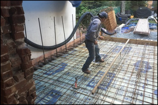
The concrete is offloaded from the chute into wheelbarrows (photo, left), then wheeled through the 40-foot-long home. Here (photo, right), the concrete was poured into the addition’s footing forms. Remodeling in the city, the author doesn’t have convenient access to the site or the benefit of using excavation equipment—workers are used to transporting new and demoed materials with buckets and wheelbarrows.
After excavating down to the neighbor’s footings on either sid…
After excavating down to the neighbor’s footings on either side of the planned addition, new 12-inch-by-30-inch footings were formed against the existing. For the footing-to-block-frost-wall connection, vertical #5 L-shaped rebar 2 feet on-center were tied to the footing’s continuous #4 rebar (photo, left). 1/2-inch XPS foam was placed against the existing walls to act as a bond break; the concrete was directed into the forms with the aid of a sheet of plywood (photo, right).
New 12-inch-block frost walls are spaced an inch off the neighbo…
New 12-inch-block frost walls are spaced an inch off the neighbor’s walls and placed on the outside edge of the new footings (photo, left). Galvanized metal truss reinforcement was installed on top of the second course to provide lateral strength, shown here on the home’s “gable-end” frost wall (photo, right).
After three courses of 12-inch-block were laid up for the frost …
After three courses of 12-inch-block were laid up for the frost walls, 2-inch XPS rigid foam was placed on the block’s interior face; then the under-slab native soils were leveled and compacted (photo, left). Crushed stone was infilled to the top of the frost wall, and then 2-by stock was installed to form the slab’s edge (photo, right).
The architect’s initial structural design called for a crawlsp…
The architect’s initial structural design called for a crawlspace under a framed first floor supported by block frost walls, but the city’s zoning administrator required slab-on-grade construction. The resulting structural redesign called for a robust 6-inch-thick slab reinforced with two layers of heavy-duty welded wire mesh. The slab tied into the 12-inch-thick-block frost walls with #5 L-shaped rebar placed 12 inches on-center. Two-inch XPS rigid foam was placed over the crushed-stone base; the foam’s seams were taped.
Documenting existing conditions. When you’re working in an urban environment with tight lots and shared party walls, it’s best to foster a cooperative relationship with your client’s neighbors. Prior to construction, I have a meeting with the abutting neighbors in their homes to review what our client’s goals are. This is more than a courtesy call. It allows us to swap contact information to keep the lines of communication open, while also giving me the opportunity to check out the condition of their homes. I want to avoid being wrongfully accused of cracking a wall, or worse, so I take photos of the neighbor’s property and of the city-owned sidewalk area out front to establish a baseline of preconstruction conditions.
Case in point, on this project, we started out by demolishing an existing 8-by-10-foot block addition off the kitchen. While removing the addition’s block frost walls, we noticed the neighbor’s two-story addition was built on top of an old, undersized footing. Hoboken row houses typically had one-story additions (similar to the one we removed), which served as kitchens back in the day. Around the time the neighbor’s two-story addition was built, some 30 or 40 years ago, Hoboken was a depressed area. Row houses were haphazardly split up into multifamily homes and boarding houses, and often the work was not done under any municipal supervision. Upon discovery, we notified the project architect and photographed the neighbor’s marginal footings.
Building After a Storm of Regulations The architect’s initial structural design called for a crawlspace under a framed first floor supported by block frost walls, but the city’s zoning administrator made us switch to slab-on-grade construction. I can only guess the reason was to avoid having mechanicals located below grade and thus susceptible to flooding. On a lot of levels, we’re still dealing with the aftermath of Hurricane Sandy, which flooded 60% of Hoboken for days in 2012. Many new building regulations were passed in the wake of that event. The resulting structural redesign called for a heavily reinforced 6-inch-thick slab tied into heavily reinforced frost walls and two-story block walls—this was a beefy shell.
Buckets and wheelbarrows. All the demolition and masonry work was jointly coordinated by our project foreman, Danny DoCouto, and our masonry sub, Victor Bezama, of FPV Contracting Co. Working in the city, we don’t have the benefit of using excavation equipment. Our foundation prep work is done old-school—by hand with shovels. All demoed rubble and excavated soil had to be carried out in buckets and wheelbarrows through a garden-level (basement) front window or door. Conversely, all building materials, such as block and concrete mix, had to be carried in by hand or wheelbarrow from small staging areas on the street-side sidewalk.
The architect’s initial design called for a crawlspace under a framed first floor supported by block frost walls, but the city’s zoning administrator required slab-on-grade construction. The resulting structural redesign called for a robust 6-inch-thick slab reinforced with two layers of heavy-duty welded wire mesh, the slab tied into the 12-inch-thick-block frost walls with #5 L-shaped rebar placed 12 inches on-center. 2-inch XPS rigid foam was placed over the crushed-stone base, the foam’s seams were taped.
The foundation. We excavated down to the neighbor’s footings on either side of our planned addition, then formed our new 12-inch-by-30-inch footings against them. For the footing-to-frost-wall connection, we tied vertical #5 L-shaped rebar 2 feet on-center to the footing’s continuous #4 rebar. We placed 1/2-inch XPS foam against the existing walls as a bond break, then wheelbarrowed in concrete from a mixer truck parked street-side.
Our 12-inch-block frost walls were placed about an inch away from the neighbor’s existing walls—they sat off-center on the outside edge of the new footings. We installed galvanized metal truss reinforcement on top of the second course to provide lateral strength. After we laid up three courses, we placed 2-inch XPS rigid foam on the block’s interior face, then leveled and compacted the under-slab native soil. We infilled with crushed stone to the top of the frost wall, then installed 2-by stock to form the slab’s edge.
For the under-slab insulation, we placed 2-inch XPS rigid foam over the crushed-stone base and taped the seams. The architect’s structural redesign called for a robust 6-inch-thick slab reinforced with two layers of heavy-duty welded wire mesh tied into the 12-inch-thick-block frost walls, with #5 L-shaped rebar placed 12 inches on-center.
1
of 10
The addition’s two-story walls were built with 8-inch block an…
The addition’s two-story walls were built with 8-inch block and reinforced with continuous #5 rebar (running from footing to top of wall) embedded in the footings 2-feet on center. The block cores were infilled at all vertical rebar locations with mortar. Two bond beams (coordinated with our ledgers placed at floor levels) were also filled solid.
Bond beams were reinforced with continuous horizontal #5 rebar, …
Bond beams were reinforced with continuous horizontal #5 rebar, and then grouted solid with mortar (photos left, right).
Two W8 steel I-beam lintels (photo, right) were installed in the…
Two W8 steel I-beam lintels (photo, right) were installed in the addition’s back wall (the top lintel is hidden by staging). An important part of the addition/renovation was to introduce natural light into the long, narrow home by opening up the entire back wall and installing large slider doors. Here (photo, left), a worker cuts an I-beam to length with a gas-powered cut-off saw.
A fairly complex steel-lintel assembly designed by the architect…
A fairly complex steel-lintel assembly designed by the architect was pieced together to carry the existing three-wythe-thick exterior brick wall (photo, left). The assembly featured structural steel channels spanning the opening, with tube steel needle beams (fed in perpendicular to the wall) welded to the top of the channels and ½-inch plate steel welded to the bottom. This was a more elaborate process than the author was used to, but it was effective (photo, right).
3×10 ledgers (with pre-installed joist hangers) were anchored to…
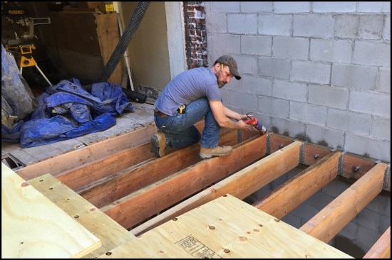
3×10 ledgers (with pre-installed joist hangers) were anchored to the wall’s floor-level bond beams. Prior to lifting and securing the 3×10 ledgers in place, peel-and-stick membrane was applied to the back of the ledger and holes were pre-drilled at the expansion bolt locations. While the ledger was temporarily held in place with 2×4 bracing, Hilti HIT-HY 70 two-component epoxy was injected into the holes using a Hilti HDM 500 manual dispenser gun. An expansion bolt was inserted and then tightened it down. After a little while, the epoxy cured and the anchor connections were rock hard.
For the addition’s parlor-level (second floor) framing, 3×10 j…
For the addition’s parlor-level (second floor) framing, 3×10 joists were flush-framed to 3×10 ledgers anchored to the block wall’s bond beams. The architect’s initial design called for the 16-inch-on-center floor framing to be left exposed to the garden-level (basement) living room below, but the ceiling ended up being covered with drywall to run and hide wiring and mechanicals.
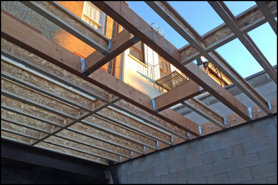
The roof framing was flushed-framed similarly to the addition’…
The roof framing was flushed-framed similarly to the addition’s parlor-level floor, but with TJIs and an LVL box-out for a skylight.
The top of the parapet (block) wall was capped with a 2-inch-thi…
The top of the parapet (block) wall was capped with a 2-inch-thick capstone.
The roof system consisted of a plywood deck with tapered roof in…
The roof system consisted of a plywood deck with tapered roof insulation (pitched toward a corner roof drain) and a TPO single-ply membrane.
The exterior was finished off with brick veneer on the rear faç…
The exterior was finished off with brick veneer on the rear façade (photo, right), and stucco on the right-hand side façade (the neighbors allowed access to apply the stucco from their second-story deck). A spiral egress stair was installed to provide access from the parlor-level (second floor) kitchen to the backyard (photo, left).
Block walls. The two-story-plus-high walls were built with 8-inch block. We ran continuous #5 rebar, placed 2 feet on-center, from the footing to the top of the wall and infilled the block cores with mortar at the vertical rebar locations. As we laid up the wall, we incorporated two W8 steel I-beams into the blockwork. The I-beams served as lintels for the addition’s opened-up back wall (large slider doors provided abundant natural light into the home).
At the second-floor and roof levels, we installed bond-beam courses, which helped tie the walls together and provided solid masonry for anchoring our flush-framed floor and roof ledgers to the wall. A third bond beam was installed at the top of the wall. We ran continuous horizontal #5 rebar in the bond-beam channel (tied to vertical rebar), then grouted the channel solid with mortar.
Workers hoist a wall-to-wall steel I-beam lintel in place; the addition’s back wall is opened up to provide as much natural light into the home’s interior as possible.
Flush-framed joists. For the addition’s parlor-level (second floor) framing, we installed 3×10 joists flush framed to 3×10 ledgers anchored to the block wall’s bond beams. The architect’s initial design called for the 16-inch-on-center floor framing to be left exposed to the garden-level (basement) living room below, but we ended up covering the ceiling with drywall to hide wiring and mechanicals.
Prior to lifting and securing the 3×10 ledgers in place, DoCouto installed the joist hangers and applied peel-and-stick to the back of the ledger, then predrilled holes for the expansion bolts. Of note: We followed the structural plans and drilled the holes in-line (rather than in a staggered pattern) and later got dinged by the building inspector for the ledger fastening. The architect had to provide a letter to the city stating that the 3×10 ledgers were structurally sound and wouldn’t split.
DoCouto held the ledger in place with 2×4 bracing and then injected Hilti HIT-HY 70 two-component epoxy into the holes with a Hilti HDM 500 manual dispenser gun. He then inserted the expansion bolt, tightened it down, and moved on to the next one. After a little while, the anchor connections hardened like a rock, and we were able to frame the floor.
We flushed-framed the roof similarly, but with TJIs and an LVL box-out for a skylight. Our roof system consisted of a plywood deck with tapered roof insulation (pitched toward a corner roof drain) and a TPO single-ply membrane.
The addition’s parlor-level (second floor) 3×10 joists were flush framed to 3×10 ledgers. The ledgers were anchored to the block wall’s bond beams with two-part epoxy is injected into predrilled holes. Expansion bolts were inserted and then tightened it down. After a little while, the epoxy cured and the anchor connections were rock hard.
Exterior cladding. We finished off the exterior with brick veneer on the rear façade, and stucco on the right-hand side. For the stucco, the neighbors allowed us access to work from their deck, which was in marginal shape. But I took lots of “before” photos to document its condition and carefully protected the deck from any damage, so we managed to finish without incident.