Problem-solving is a big part of my job as a home builder, and even after more than 40 years in the business, I’m still running into new problems to solve. Recently, for example, we were building a two-story home with a symmetrical front elevation and a staircase off the front entry. The stairs drawn on the floor plan showed three treads up to a lower landing, then a turn to follow the exterior wall for 10 treads to another landing, with a turn to three more treads that led up to a bridge across the two-story living room.
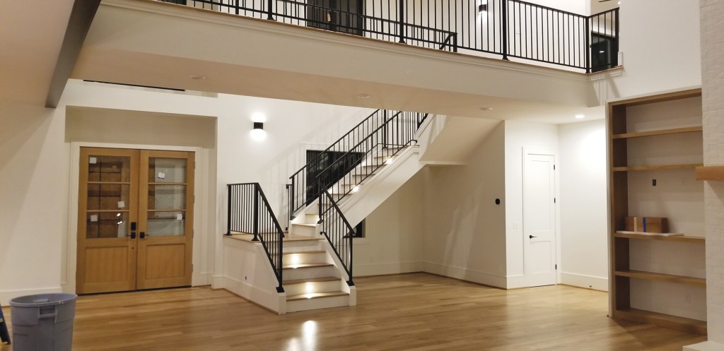
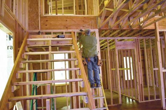
Because the stairs would run diagonally across one of the symmetrical windows beside the front door, the framing crew didn’t frame that window opening. Of course, this wasn’t a satisfactory solution for my client. But adjusting the stair location wasn’t an option either, because it was locked in by the front door on the first floor and the second-story bridge. Instead, I had to solve this present-day issue by relying on an old, historic solution: Frame and install the window per the original plans to maintain the symmetry of the front elevation, and float the stairs about 10 inches off the wall (the run of one stair tread) to miss the window.

The entry to the home was flanked by a pair of windows, one of which was located right in front of a staircase leading up to the second level; to preserve the home’s symmetrical fenestration, the stairs needed to be spaced away from the wall.
My client loved the idea, but my design solution presented a structural challenge because only one side of the upper landing would be attached to a wall. Not only would the landing have to carry the entire load for the main run of stringers—none of which would now be attached to a wall—but it would also need to support loads from the short run of stairs up to the bridge. That is a lot to ask from a landing with no visible means of support.
Layout
I first considered supporting the landing either with some sort of metal structure or with framing cantilevered back into the entry closet. But then I recalled some of the historic homes I’ve toured while on vacation over the years, several of which featured similar floating stairs. So I knew it could be done; all I had to do was figure out how those carpenters had managed to build their solid but unsupported staircases.
As I was working on the layout, I realized that the stringers for the unattached section of the stairs could work like a diagonal brace for the upper landing. If the stringers were rigid enough and none of my connections failed, the landing couldn’t move. The same was true in reverse for the short upper run. So I decided to give this method a try, while keeping the option of cantilevering into the entry closet as a backup plan.
I began by calculating the total number of treads needed for the stairs, which would determine the run for each section. We would be using 11 1/2-inch-wide hardwood treads, so I figured 10 inches of run per tread to allow for a 1 1/2-inch overhang.
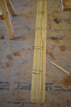
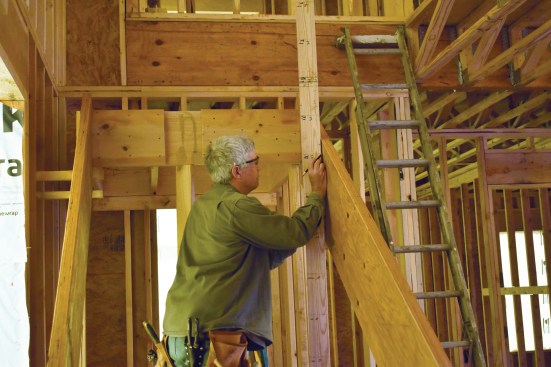
The author began by marking the stair’s vertical layout, including each tread, on a story pole.
The story pole also included the elevations of the lower and upper landings.
Next, I plumbed down from the face of the bridge and marked the layout on the floor as accurately as I could, starting with the front of each riser. In my layout, I allowed for 48-inch-wide landings and treads. With the 10-inch spacing off the wall, the starting tread moved farther out into the living room, which ended up allowing more room for a piece of furniture that would back up to the stairs.
Whenever I’m laying out stairs, I like to mark the layout on a story pole. This allows me to accurately record finish floor heights, landing locations, and the elevation of each tread. It becomes my blueprint for building the stairs.
Landing Platforms Connected by Solid Stringers
Since the home was fairly contemporary, I was able to design a staircase with housed treads instead of more traditional mitered returns, which meant that the two outside stringers wouldn’t have to be notched. To provide strong diagonal bracing, we used 1 3/4-inch-by-16-inch LVLs for the stringers and made every connection with plenty of 2-by blocking, lots of construction adhesive, and structural screws.
Solid stringers were important to the structural integrity of the assembly, but I also wanted to make sure that the bottom landing they attached to wouldn’t move. We determined the height of the platform using the story pole, and during the landing’s construction, we glued and screwed its support walls to the wood subfloor, then reinforced the landing with a layer of OSB glued and screwed inside the framing. We used 2x12s to build the landing platform, which we glued and screwed to the support walls. Finally, we glued and screwed 3/4-inch OSB sheathing to the framing for the platform top; in all, we used about three large tubes of construction adhesive in the landing’s construction.
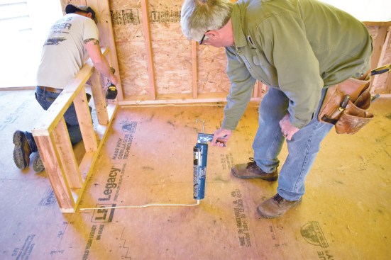
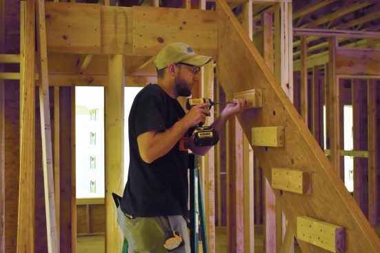
The author and his crew used plenty of structural screws and construction adhesive as they framed each landing.
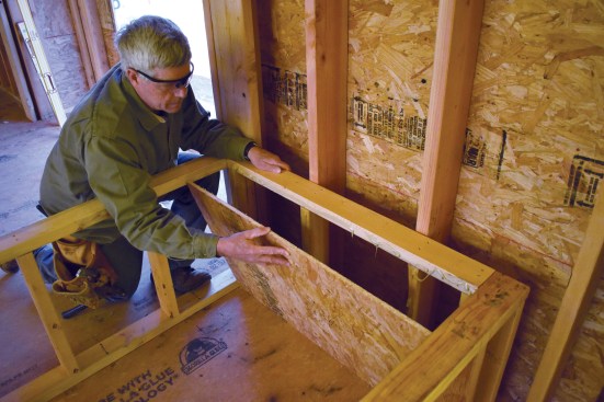
OSB sheathing was glued and screwed to the inner faces of the short walls supporting the landing platform.
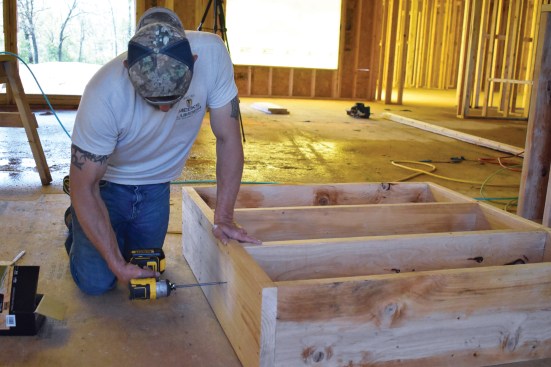
The lower landing platform was framed with 2x12s and held together with structural screws and glue.
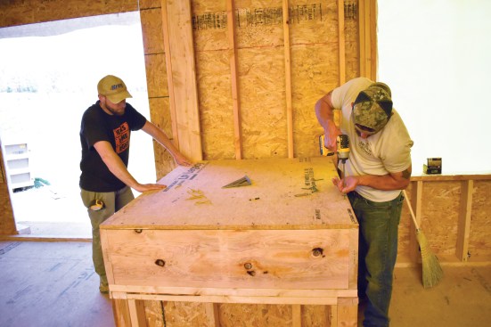
After fastening the platform to the support walls, the crew sheathed it with 3/4-inch plywood screwed and glued to the framing.
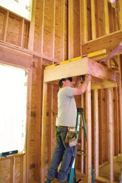
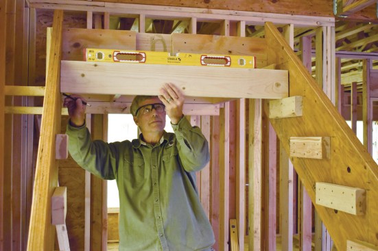
We also used 2x12s to build the platform for the floating upper landing, again using both construction adhesive and structural screws to strengthen the assembly. Before screwing the framed platform to the closet wall framing, we added plenty of blocking between studs on the flat for added attachment strength and reinforced the connection with construction adhesive. We installed a temporary ledger to the framing to help orient and level the platform and used a couple of temporary 2×4 legs to support the platform and hold its outside edge in position while we installed the stringers.
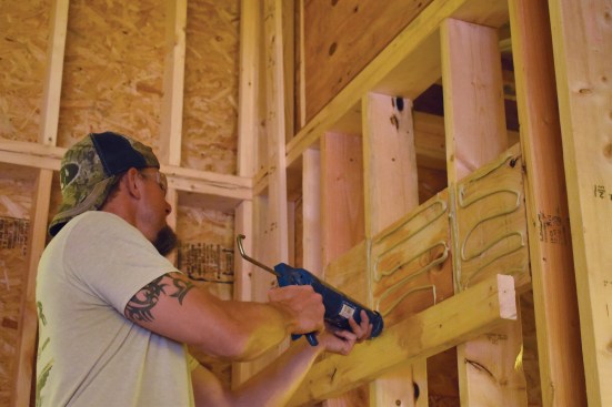
Blocking and construction adhesive was added to the wall framing prior to installation of the upper landing. Note the temporary 2×4 support ledger.
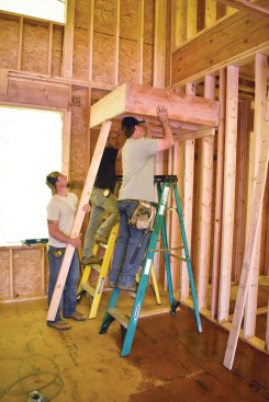
The crew propped the upper landing up with temporary supports while they fastened it to the framing.
The supports remained in place until the LVL stair stringers were measured, cut, and installed.
Next, we carefully measured the diagonal distance between the top edges of the upper and lower platforms and, based on the 7 5/8‑inch rise and 10-inch run of the treads, laid out the upper and lower plumb cuts on the two outside stringers that run between landings. After double-checking their fit, we fastened the stringers to the upper and lower landings with glue and structural screws.
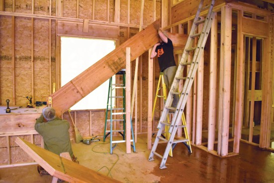
The upper and lower landings are structurally connected by a pair of 1 3/4-inch-by-16-inch-deep solid LVL stringers.
Using the horizontal layout I had marked on the floor, the vertical layout on my story pole, and a spirit level, I marked the stringers with the points where the top of each riser met the bottom of a stair tread and then marked horizontal lines for each stair tread. Next, I glued and screwed 2×4 cleats to the outer stringers at each location to support the stair treads.
The center stringer had to be notched, so I laid out the positions of each tread and riser on an LVL and made the sawtooth cuts. Before permanently attaching it, I tacked the stringer in place and double-checked the layout with a straightedge.
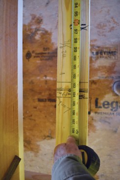
Using the story pole for reference, the author marked the tread locations on the inside stringer.
Then a crew member glued and screwed 2-by cleats to the stringer to support the treads.
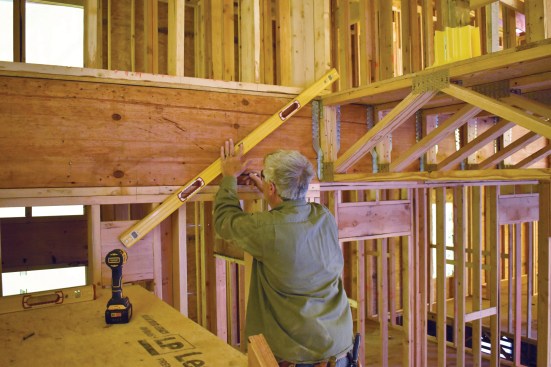
Using a spirit level and a straight 2-by, the author transferred the tread layout to the outside stringer.
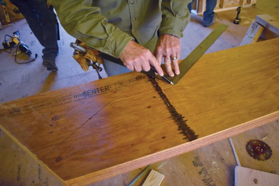
The 16-inch-wide LVL used for the middle stringer needed to be notched for the treads and risers.
On the short, upper run of stairs, the left-hand stringer could be fastened to the wall framing, so I made sure it was well-attached with structural screws and plenty of construction adhesive. Otherwise, I just repeated the process from the middle run of stairs at the top and bottom. I always wait until close to the end of the job to install hardwood treads, so we cut temporary treads out of framing lumber.
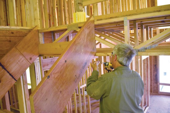
With the upper landing locked into position, the author laid out the inside stringer for the short run of stairs to the upper level (top left). He glued and screwed the stringer to the framing (top right), then installed additional blocking and the outside stringer (above). To provide access to the upper level during construction, crew members installed temporary 2-by treads (right).
One more step that we took to strengthen the stairs was to glue and screw a layer of 7/16-inch OSB to the bottom of the stringers, prior to drywall. I’ve built several unsupported curved stairs and have found that this measure adds a lot of strength to the assembly, so I figured it had to help this stair too.
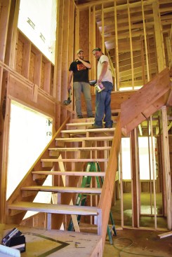
Finally, we pulled the temporary legs from the landing to test the stairs for strength. I was pretty sure we were going to be in good shape, but I sent two guys up to the landing and stood at the bottom looking for movement. It was as solid as any stair I have ever built.
An interesting note: Even though I had worked as a carpenter for more than 40 years before building my first unsupported stair, within a month of completing this staircase, I used some of the same principles on another job. It really is an amazing look, so I’m betting that I’ll be building another one soon.
Photos by Gary Striegler and Mark Gannaway.